CNC Vertical Machining Center Structure
1. Introduction
The CNC vertical machining center (VMC) stands as a cornerstone of modern precision manufacturing. With its spindle mounted vertically and the workpiece secured on a horizontal table, it executes complex milling, drilling, tapping, and contouring operations through coordinated X-, Y-, and Z-axis motion. Consequently, VMCs are essential across industries—from mold-making and aerospace to automotive and general machinery—particularly for low- to medium-volume production of high-precision components.
Compared to horizontal machining centers, VMCs offer a smaller footprint, intuitive workpiece setup, natural chip evacuation, and easier operation and maintenance. In contrast, basic CNC mills lack an automatic tool changer (ATC) and tool magazine. Therefore, they cannot perform multi-operation machining in a single setup. By integrating an ATC, VMCs significantly boost productivity. When evaluating equipment, buyers often research cnc machine price, browse listings for cnc machine for sale, or consider used cnc machine for sale units. Meanwhile, job shops rely on these machines to deliver dependable cnc machining services. This article systematically breaks down the physical structure of the VMC—from foundational components to core functional modules—so that engineers and decision-makers gain the technical insight needed for selection, installation, troubleshooting, and maintenance.
2. Machine Layout and Coordinate System
2.1 Vertical Configuration
The defining feature of a VMC is its vertically oriented spindle, with the cutting tool advancing downward along the Z-axis. As a result, chips fall away naturally under gravity, which simplifies chip management and reduces the risk of recutting. Moreover, this layout gives operators a clear view of the work zone, making setup and monitoring more straightforward.
For workshops with space or budget constraints, a small cnc machine or desktop cnc mill may seem appealing. However, these lighter-duty machines lack the rigidity, travel, and power required for serious metal cutting and are better suited to prototyping or non-ferrous materials.
2.2 Coordinate System and Axis Assignment
Per ISO 841 standards, VMCs use a right-handed Cartesian coordinate system:
- Z-axis: aligned with the spindle (positive upward)
- X-axis: left–right from the operator’s perspective (positive to the right)
- Y-axis: front–back (positive away from the operator)
Most standard models are 3 axis machining systems, where the table moves in X and Y while the spindle head travels in Z. In contrast, high-end variants evolve into 5 axis cnc machine configurations by adding rotational axes (A, B, or C). This enhancement enables the machining of complex geometries in a single setup—ideal for aerospace impellers or medical implants.
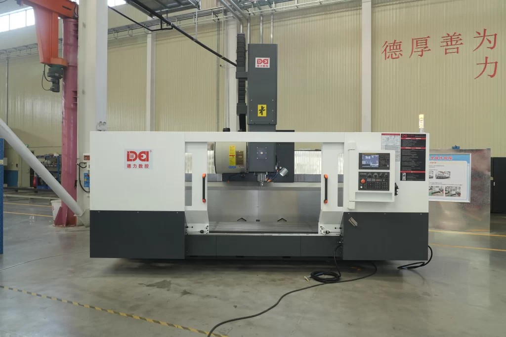
2.3 Common Structural Configurations
VMCs come in three primary layouts:
- Fixed-column: The column is cast integrally with the base, and the table moves in X and Y. This design offers high rigidity—ideal for precision work.
- Moving-column: The column traverses along the base (typically in X), while the table moves only in Y. Consequently, it better accommodates large or heavy parts.
- Gantry-style (compact): Dual columns bridge the base and support a cross-rail that carries the spindle. Thus, it combines rigidity with vertical accessibility.
Importantly, these are industrial-grade cnc milling machines—not to be confused with lightweight cnc router machines, which lack the structural integrity for metal removal.
3. Base Structure
3.1 Base (Bed)
The base forms the foundation of the entire machine. Because its rigidity and thermal stability directly determine long-term machining accuracy, industrial VMCs use high-grade gray cast iron (typically HT300 or better). Manufacturers stress-relieve the castings at 550–600°C to reduce residual stresses to ≤30 MPa.
Additionally, the base features a closed-box cross-section with orthogonal ribbing—rib thickness usually measures 60–80% of the wall thickness and spacing runs 300–500 mm apart. Engineers precision-grind critical guideway mounting surfaces to ≤0.02 mm/m flatness and Ra ≤ 0.8 μm. This robust design enables cnc milling machines to maintain micron-level accuracy under heavy cutting loads.
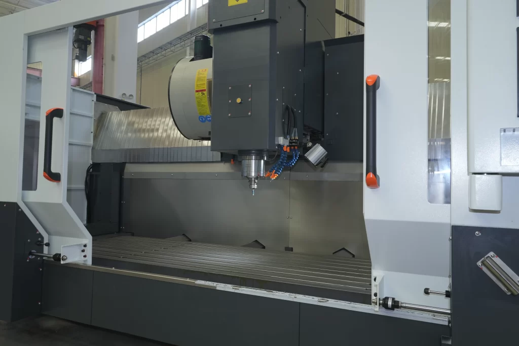
3.2 Column
The column rises vertically from the rear of the base and guides the spindle head’s Z-axis motion. Designers may cast it integrally with the base or bolt it on—each approach balances rigidity against manufacturability and shipping logistics.
Internally, the column houses wiring, hydraulic lines, and coolant passages. To minimize thermal distortion, many designs incorporate symmetrical cooling channels that circulate temperature-controlled fluid (±0.5°C), keeping thermal gradients below 1°C per meter of height.
4. Axis Drive Systems
4.1 X- and Y-Axis Feed Mechanisms
The X/Y motion system typically consists of:
- Y-axis: the table moving front–back on the saddle
- X-axis: the saddle moving left–right on the base
Manufacturers equip these axes with high-precision linear guideways (ball or roller type) with C0–C3 preload. For example, an 800-mm travel machine commonly uses 4–6 carriage blocks per axis, rated for ≥50 kN dynamic load and ≥800 N/μm stiffness.
They also install pre-stretched ball screws (32–50 mm diameter, 10–20 mm lead) to drive the axes. Technicians fix both ends to prevent buckling and apply a calculated pre-tension—typically 1/3000 to 1/2000 of the free length—to compensate for thermal expansion and mechanical compression.
4.2 Z-Axis Feed Mechanism
The spindle head moves vertically along dual, symmetrically mounted guideways to resist overturning moments. Given its substantial mass (200–600 kg), engineers incorporate a counterbalance system—either nitrogen cylinders or mechanical weights with pulleys—to reduce servo load and improve responsiveness.
They often center-mount the ball screw to align it with the head’s center of gravity, thereby minimizing eccentric loading.
5. Spindle Assembly

5.1 Spindle Types and Drives
The spindle delivers cutting power and directly influences process capability:
- Belt-driven: High torque at lower speeds (e.g., 6,000 rpm, 100+ N·m)—ideal for roughing steel.
- Direct-coupled: The motor connects rigidly to the spindle, which reduces vibration and improves finishing quality.
- Integrated motor (electric spindle): The rotor builds into the spindle shaft, enabling speeds up to 40,000 rpm for high speed machining of aluminum or composites.
Note: A cnc lathe machine rotates the workpiece, not the tool—its purpose and structure differ fundamentally from a VMC.
5.2 Tool Interface and Drawbar
Standard tooling interfaces include BT (7:24 taper) and HSK (hollow shank, 1:10 taper). A stack of Belleville washers (typically providing 15–25 kN of clamping force) securely holds the tool in place, while hydraulic or pneumatic pressure actuates the release mechanism. As a result, the system achieves tool-to-spindle repeatability of ≤±0.002 mm.
5.3 Thermal Management
Spindle heat can cause Z-axis thermal growth of 10–30 μm over two hours. To counter this, coolant circulates through internal spiral channels (3–8 L/min, ±0.5°C control). Operators install PT100 sensors at the front and rear bearings to feed real-time data to the CNC for thermal compensation.
6. Automatic Tool Changer (ATC)
6.1 Tool Magazine Types
The ATC enables true unattended multi-operation machining:
- Umbrella-type: 10–24 tools, simple and cost-effective—common on small cnc machine platforms.
- Disc-type: 20–40 tools, faster indexing, used in production environments.
- Chain-type: For >40 tools, often in flexible manufacturing cells.
This capability transforms the VMC into a full-fledged cnc machine shop workhorse capable of delivering end-to-end cnc machining services.
6.2 Tool Change Mechanism
The tool change sequence—spindle orientation, Z-axis positioning, magazine rotation, and tool exchange—takes 3–6 seconds. Engineers maintain repeatability at ≤±0.01 mm via mechanical stops or closed-loop servo control.
6.3 Tool Identification
To prevent errors, operators identify tools via contact pins (binary-coded) or RFID tags embedded in the tool holder—ensuring the right tool is always in the right place.
7. CNC and Drive System Integration
Modern VMCs use fully digital servo drives with 20+ bit absolute encoders (1,048,576 pulses/rev), which enables absolute position retention after power loss.
High-accuracy models often add linear scales (0.1–1 μm resolution) for full closed-loop control, thereby compensating for ball screw pitch error, thermal drift, and backlash. Operators typically program the machine via cnc programming software (e.g., Mastercam, Fusion 360), and they usually undergo formal cnc machine training to master setup, probing, and troubleshooting.
8. Auxiliary Systems
8.1 Coolant System
- Flood coolant: 20–100 L/min at 0.3–0.6 MPa for general milling.
- Through-spindle coolant (TSC): 3–7 MPa for deep drilling or difficult materials—which requires rotary unions rated for high pressure.
8.2 Lubrication System
A centralized automatic lubrication system delivers precise grease doses (0.2–0.5 cm³ per point) every 30–120 minutes to guideways and ball screws. If lines clog, the system triggers immediate alarms.
8.3 Chip Removal and Protection
Stainless steel telescopic or bellows-type covers protect moving components (IP54 rating). Chain-type chip conveyors handle ≥50 L/min of swarf, feeding into a tank (300–800 L) with settling zones and filters.
Important distinction: Woodworking relies on cnc wood router or cnc router for wood systems, which use dust collection—not coolant—and lack the rigidity for metal. Similarly, cnc machine woodworking and cnc router woodworking equipment should never be used for steel or titanium. Other CNC variants, such as the cnc plasma cutter or cnc laser cutter, use thermal processes entirely different from mechanical milling.
9. Precision Assurance Measures
Manufacturers validate VMCs per ISO 230 standards:
- Positioning accuracy: ≤±5 μm over 300 mm (laser interferometer)
- Reversal error: ≤4 μm
- Spindle runout: ≤0.005 mm at 300 mm from face
- Table flatness: ≤0.02 mm over 500 mm
Achieving this level of precision requires hand scraping or precision grinding of guideway surfaces (≥12 contact points per 25×25 mm²) and meticulous alignment of ball screws and couplings (concentricity ≤0.02 mm).
For companies seeking external support, searching cnc machining near me or cnc machine shops near me helps locate local providers equipped with high-precision cnc milling machines.
10. Conclusion
The VMC is a masterpiece of mechanical engineering—where cast iron, precision mechanics, thermal control, and digital intelligence converge to deliver consistent, high-quality results. Every component, from the ribbed base to the thermally managed spindle, is engineered for rigidity, accuracy, and reliability.
In practice, a skilled cnc machine operator must understand this structure to perform daily checks and preventive maintenance. Employers frequently post cnc machinist jobs and benchmark offers against prevailing cnc machine operator salary data. Meanwhile, buyers weighing a capital investment carefully analyze cnc machine price, compare new cnc machine for sale options, and evaluate the value of used cnc machine for sale units.
Ultimately, the VMC is more than a machine—it’s the backbone of modern precision manufacturing. Understanding its structure isn’t just technical knowledge; it’s the foundation of smart investment, efficient operation, and sustained competitiveness.