What Materials Can Be Machined on a Vertical Machining Center
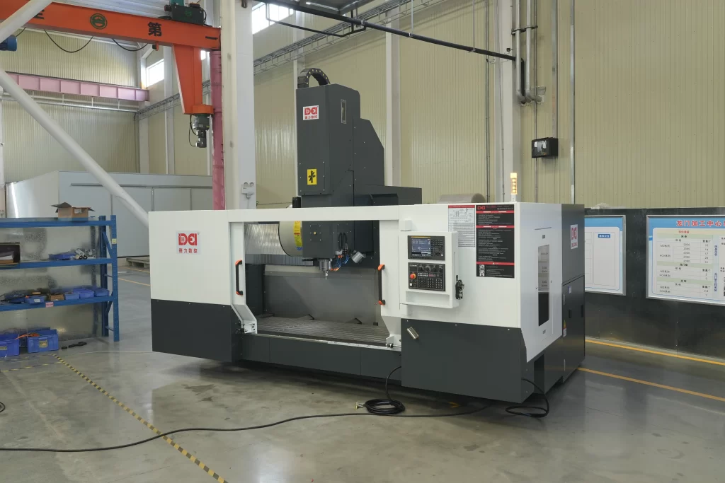
The vertical machining center stands at the heart of modern precision manufacturing, serving as a go-to solution for high-accuracy, medium-to-low volume production across industries such as aerospace, automotive, medical devices, and mold making. With its spindle oriented vertically and a compact, rigid structure, the vertical machining center excels at milling, drilling, tapping, and contouring complex parts with efficiency and repeatability.
As industrial demands evolve and new materials emerge, the capabilities of vertical machining centers have expanded far beyond traditional carbon steels. Today’s machines routinely handle everything from lightweight aluminum alloys to tough titanium, and even non-metallic composites like carbon fiber-reinforced plastics. But not all materials can be processed effectively on every machine. Success depends on a careful balance between material properties, tooling strategy, cutting parameters, and—critically—the machine’s technical specifications.
Understanding the Machining Capabilities of a Vertical Machining Center
A typical vertical machining center features three-axis motion (X, Y, Z), with the spindle mounted vertically above a movable worktable. This configuration makes it ideal for face milling, pocketing, drilling, and 2.5-axis contouring. Advanced models may include a fourth axis (rotary table) or full five-axis simultaneous motion, enabling the machining of complex freeform surfaces.
Key strengths of the vertical machining center include:
- High positioning accuracy (repeatability within ±0.003 mm)
- Rigid frame design that resists deflection under load
- Fast automatic tool changers (ATC) with tool-to-tool times as low as 2 seconds
- Thermal stability through symmetrical construction and real-time compensation algorithms
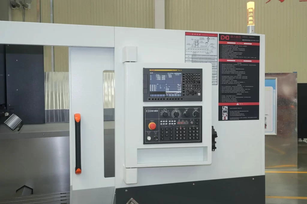
- CNC systems capable of processing complex toolpaths with look-ahead control
However, these capabilities must align with the demands of the material being cut. For instance, machining titanium requires high torque at low speeds and effective heat removal, while carbon fiber composites demand high spindle speeds and specialized tooling to prevent delamination. In short, the machine is only one part of a larger system—material, tool, process, and equipment must all work in harmony.
Key Factors Influencing Machinability
Before diving into specific materials, it’s essential to understand the core factors that determine how well a material performs on a vertical machining center.
2.1 Hardness and Strength
Material hardness—measured in Brinell (HB) or Rockwell (HRC)—directly affects cutting forces. High-hardness materials like quenched tool steel (HRC > 60) require substantial power and rigidity. If the machine lacks sufficient structural stiffness, chatter occurs, leading to poor surface finish and accelerated tool wear.
Tensile strength (UTS) also plays a role. Materials like Inconel 718 (UTS ≥ 1200 MPa) generate extreme resistance during cutting. To manage this, vertical machining centers should have a spindle power of at least 15 kW and employ step-down roughing strategies to reduce per-pass load.
2.2 Thermal Conductivity and Expansion
Materials with low thermal conductivity—such as titanium (≈7 W/m·K)—trap heat at the cutting zone, where temperatures can exceed 800°C. This localized heating accelerates tool wear and risks altering the microstructure of the workpiece.
High thermal expansion coefficients, common in aluminum (≈23×10⁻⁶/°C), mean even small temperature changes cause measurable dimensional shifts. A 200 mm aluminum part heated by 30°C can expand by nearly 0.14 mm—well beyond typical tolerance bands. Therefore, thermal management in machining is crucial to maintain dimensional stability and surface finish.
2.3 Ductility and Toughness
Highly ductile materials like austenitic stainless steel (e.g., 304) produce long, continuous chips and are prone to built-up edge (BUE). BUE alters the effective rake angle of the tool, causing fluctuating cutting forces, increased vibration, and degraded surface quality.
Soft, sticky materials like pure copper tend to “string” or smear during cutting. Sharp, polished cutting edges and aggressive feed rates help prevent material adhesion.
2.4 Chemical Reactivity
Some materials react chemically with tool substrates at elevated temperatures. Titanium, for example, readily bonds with cobalt in standard tungsten carbide tools, leading to rapid crater wear and edge chipping. To avoid this, use coatings like AlTiN or tools made from submicron-grade carbide with enhanced oxidation resistance.
2.5 Machine Requirements by Material
Different materials place distinct demands on machine configuration:
- Spindle speed range: Aluminum benefits from high RPM (12,000+), while titanium needs low speed with high torque.
- Cooling system: Stainless and titanium require high-pressure internal coolant (≥50 bar) to flush chips and dissipate heat.
- Tool interface: HSK-A63 or BT40 toolholders offer better rigidity and balance than CAT40, especially for heavy cuts.
- Control system: Complex contours require CNCs with advanced look-ahead and jerk control to maintain smooth motion.
Common Materials Processed on a Vertical Machining Center
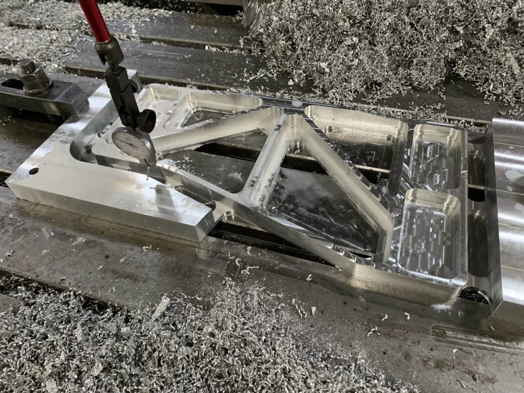
3.1 Aluminum Alloys
Aluminum alloys—such as 6061-T6 (UTS ≈ 310 MPa) and 7075-T6 (UTS up to 570 MPa)—are widely used in aerospace, electronics, and transportation due to their excellent strength-to-weight ratio and good machinability.
Challenges: Despite being soft, aluminum has a tendency to stick to cutting edges, forming built-up edge that degrades surface finish. Thin-walled components are susceptible to deflection and vibration.
Recommended Parameters:
- Spindle speed: 8,000–20,000 rpm
- Cutting speed: 300–1,200 m/min
- Feed per tooth: 0.1–0.3 mm/tooth
- Depth of cut (ap): ≤5 mm (rough), ≤0.5 mm (finish)
Tooling: Polycrystalline diamond (PCD) tools offer superior wear resistance and low friction for high-volume production. For general use, AlTiN-coated carbide end mills perform well.
Cooling: Minimal quantity lubrication (MQL) or compressed air is preferred to prevent galvanic corrosion from water-based coolants.
Applications: Aircraft brackets, motor housings, smartphone frames.
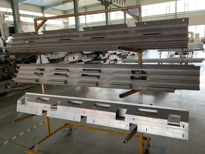
3.2 Carbon and Alloy Steels
Carbon steels (e.g., AISI 1045) and alloy steels (e.g., 4140, 4340) remain the backbone of mechanical engineering due to their strength, toughness, and cost-effectiveness.
Challenges: Medium-to-high carbon steels work-harden during cutting, especially in interrupted cuts. Alloying elements like chromium and molybdenum increase strength but also abrasiveness.
Recommended Parameters:
- Spindle speed: 4,000–8,000 rpm
- Cutting speed: 100–180 m/min
- Feed per tooth: 0.1–0.25 mm/tooth
Tooling: TiCN or TiAlN-coated carbide tools extend tool life significantly. For roughing, ceramic inserts allow dry high-speed machining.
Cooling: High-pressure emulsified coolant (≥20 bar) ensures chip evacuation and prevents re-cutting.
Applications: Gearboxes, shafts, die bases.
3.3 Stainless Steels
Stainless steels—such as 304, 316, and precipitation-hardened 17-4 PH—are valued for corrosion resistance in food processing, medical, and chemical environments.
Challenges: Austenitic grades exhibit strong work hardening—surface layers can reach twice the base hardness. Cutting zones reach high temperatures (up to 700°C), accelerating tool degradation.
Best Practices:
- Use ramping or circular entry instead of plunge cutting
- Maintain consistent depth and width of cut to avoid re-cutting hardened layers
- For finishing, use light cuts (<0.2 mm) and moderate speeds to minimize heat input
Tooling: Fine-grain carbide with AlCrN or AlTiN coating offers excellent oxidation and anti-adhesion properties.
Cutting Speed: 80–120 m/min Spindle Speed: Adjust based on tool diameter (e.g., 2,500–3,200 rpm for a 12 mm end mill)
Cooling: High-pressure internal coolant (≥50 bar) is mandatory to deliver lubricant directly to the cutting edge.
Applications: Pump bodies, surgical instruments, sanitary tanks.
3.4 Titanium Alloys
Titanium alloys—especially Ti-6Al-4V—are critical in aerospace and medical implants due to their high strength-to-density ratio, fatigue resistance, and biocompatibility.
Challenges:
- Poor thermal conductivity traps heat at the tool tip
- High chemical reactivity leads to welding or “cold welding” between tool and workpiece
- Low elastic modulus causes springback and chatter in thin sections
Recommended Parameters:
- Cutting speed: 30–50 m/min (rough), 60–90 m/min (finish)
- Spindle speed: 2,000–4,000 rpm (low-speed, high-torque mode)
- Feed per tooth: 0.05–0.12 mm/tooth
Tooling: Submicron-grain carbide (≤0.5 μm) with AlTiN coating provides the necessary hardness and thermal stability.
Cooling: High-pressure internal coolant (≥70 bar) using extreme-pressure cutting fluid is essential for heat dissipation and lubrication.
Applications: Aircraft structural joints, turbine blade roots, orthopedic implants. Achieving high accuracy in these components is essential for medical implant machining accuracy.
3.5 Copper and Copper Alloys
Copper (C11000) and brass (C36000) are used extensively in electrical and thermal applications due to their excellent conductivity.
Challenges: High ductility leads to “stringing” and burr formation. Pure copper has a low melting point (1,083°C), so excessive heat can cause localized melting.
Recommended Parameters:
- Spindle speed: 6,000–12,000 rpm
- Cutting speed: 150–300 m/min
Tooling: Uncoated or DLC (diamond-like carbon) coated carbide with large rake angles (15°–20°) and polished flutes to reduce adhesion.
Cooling: Dry cutting or air blasting is often sufficient; avoid emulsions that may corrode copper surfaces.
Applications: Electrodes, heat sinks, terminal blocks.
3.6 Engineering Plastics and Composites
With growing demand for lightweighting, materials like POM (acetal), PEEK, G10 (epoxy-glass), and CFRP (carbon fiber-reinforced polymer) are increasingly machined on vertical machining centers.
Challenges:
- CFRP is anisotropic and prone to delamination, fiber pull-out, and fraying
- Thermoplastics like POM melt easily (≈165°C), leading to smearing
- Dust is highly abrasive and poses explosion risks
Recommended Parameters:
- Spindle speed: 15,000–24,000 rpm
- Depth of cut: ≤1 mm to minimize interlayer stress
- Feed rate: 0.05–0.15 mm/tooth
Tooling: PCD or diamond-coated end mills with sharp, polished edges to shear fibers cleanly.
Cooling & Chip Removal: Dry machining with powerful dust extraction (≥1,200 m³/h) is essential to maintain air quality and prevent clogging.
Applications: Drone enclosures, insulating panels, lightweight automotive components.
Material-to-Machine Compatibility Summary
| MATERIAL | SPINDLE SPEED | COOLING METHOD | RECOMMENDED TOOLING | HP INTERNAL COOLANT? | TYPICAL SPINDLE POWER |
|---|---|---|---|---|---|
| Aluminum | High | MQL or air blast | PCD / AlTiN-coated carbide | No | 10–15 kW |
| Stainless Steel | Medium | Wet + high pressure | AlCrN / AlTiN-coated carbide | Yes (>50 bar) | 15–20 kW |
| Titanium Alloy | Low–Medium | High-pressure internal | Submicron carbide + AlTiN | Yes (>70 bar) | 20–25 kW |
| Copper/Brass | Medium–High | Dry or air blast | DLC-coated or uncoated | No | 10–15 kW |
| Engineering Plastics | High | Dry + dust extraction | PCD / diamond-coated | No | 10–15 kW |
| CFRP | High | Dry + strong suction | PCD specialized tools | No | 15–20 kW |
Real-World Case Studies
Case 1: Aerospace Aluminum Bracket Machining An aerospace supplier used a vertical machining center with a 12,000 rpm spindle to machine 7075-T6 aluminum brackets. Using a PCD face mill at 800 m/min with optimized toolpaths, cycle time dropped from 22 to 13 minutes per part. Surface finish improved to Ra < 1.2 μm, and tool life reached 300 parts per edge.
Case 2: Medical Titanium Bone Plate Machining A medical device manufacturer processed Ti-6Al-4V bone plates on a vertical machining center equipped with 20 kW spindle power and 80 bar internal coolant. A 6 mm ball-nose end mill ran at 70 m/min with MQL and temperature monitoring, keeping cutting zone temperatures below 300°C. Final parts achieved ±0.01 mm accuracy with no thermal damage, meeting biocompatibility standards.
Common Misconceptions and Practical Tips
- Myth: “Any vertical machining center can machine stainless steel.” Reality: Low-rigidity machines suffer from chatter when cutting 316L. Choose heavy-duty frames with adjustable guide preload.
- Myth: “Plastics don’t need special tools.” Reality: Standard tools dull quickly on PEEK. Use diamond-coated or PCD cutters for clean, burr-free edges.
- Best Practice: Build a material-tool-parameter database. Standardize programs for common materials to reduce setup errors and improve consistency.
Conclusion
Vertical machining centers are remarkably versatile, capable of handling a broad spectrum of materials—from soft aluminum to tough titanium and abrasive composites. However, success isn’t guaranteed by machine capability alone. It requires a deep understanding of material behavior, precise tool selection, and intelligent process planning.
By aligning machine specifications with material demands and adhering to proven machining principles—such as using high-pressure internal coolant for stainless steel, PCD tools for aluminum, and effective thermal management in machining—manufacturers can unlock the full potential of their vertical machining centers: achieving high precision, long tool life, and consistent quality. The data and case studies presented here reflect current industrial best practices and are intended to serve as a reliable reference for real-world production environments, including applications such as vertical machining centers for aerospace parts and medical implant machining.
Frequently Asked Questions
When should you choose a vertical machining center over other CNC machines?
A vertical machining center is ideal for flat, plate-like parts, 2.5-axis milling, and operations requiring frequent tool changes. It offers better chip evacuation and visibility than horizontal machines, making it well-suited for mold making, aerospace components, and low-to-medium volume production.
Can a vertical machining center handle 5-axis machining?
Yes, many modern vertical machining centers support 5-axis capability through the addition of a rotary table or trunnion fixture. This enables complex contouring and single-setup machining of intricate geometries, commonly used in aerospace and medical device manufacturing.
How does spindle power affect material selection?
Spindle power directly influences the types of materials and operations a vertical machining center can handle. A 10–15 kW spindle is sufficient for aluminum and plastics, while 20–25 kW is recommended for stainless steel and titanium to maintain cutting stability and tool life under high load.