How to Identify, Repair, and Prevent CNC Spindle Failures
You rely on your CNC machining center for accuracy and speed. When the spindle starts showing symptoms like unusual noise, increased vibration, overheating, or loss of accuracy, you risk costly downtime and product defects. DELICNC’s focus on reliability means you can spot issues early.
| Symptom | Cause | Action |
|---|---|---|
| Unusual Noise | Worn bearings | Listen for changes in sound |
| Poor Surface Finish | Spindle runout | Inspect surface finish |
| Increased Vibration | Imbalanced tooling | Measure vibration levels |
| Overheating | Bearing failure | Monitor temperature |
| Loss of Accuracy | Shaft damage | Perform calibration checks |
Taking quick steps toward CNC spindle repair keeps your production running smoothly.
CNC Spindle Function and Types
Spindle Role in CNC Machines
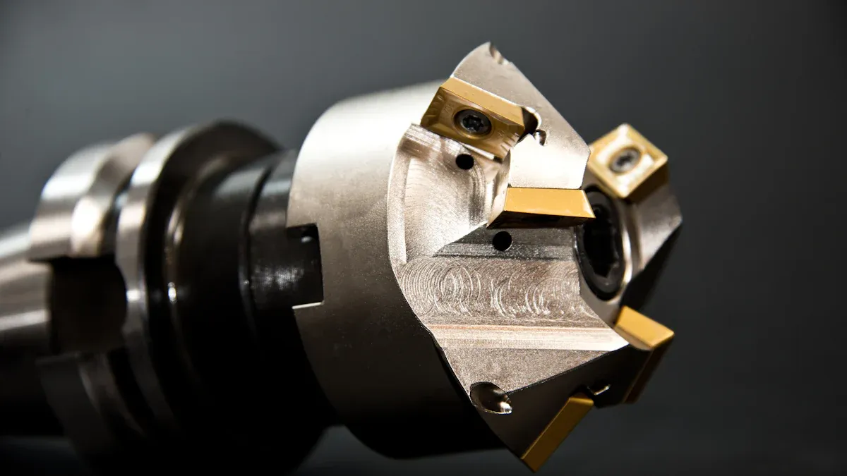
You depend on the spindle for every machining operation. The spindle holds and rotates the cutting tool, delivering the torque and speed needed to shape materials with accuracy. In DELICNC machining centers, the spindle acts as the heart of the machine. It ensures that each cut meets strict tolerances, whether you work with aluminum profiles for automotive parts or intricate components for precision manufacturing.
A CNC spindle controls the speed and force applied to the workpiece. The type of spindle you choose affects the precision and reliability of your machining process. High-speed spindles maintain accuracy at elevated RPMs, making them ideal for tasks that require fine detail. Belt-driven spindles offer greater torque, which helps when you need to cut tough materials or handle heavy-duty jobs.
DELICNC’s advanced spindle technology supports industries that demand consistent quality. Automotive manufacturers rely on these spindles for engine mounts and chassis parts. Furniture makers benefit from the ability to process wood, aluminum, and composites with speed and flexibility.
Tip: Regularly check spindle performance to maintain high accuracy and avoid costly downtime.
Common Spindle Types
You will find several spindle types in modern CNC machines. Each type offers unique advantages for specific applications. DELICNC designs its machining centers to accommodate these needs, helping you achieve the best results in your sector.
| CNC Spindle Type | Application in Manufacturing Sectors |
|---|---|
| Belt-driven spindles | General-purpose machining, suitable for wood, plastics, etc. |
| Gear-driven spindles | Cutting tough materials, handling large tools in automotive. |
| Direct-drive spindles | High-speed, high-accuracy operations in precision manufacturing. |
| Built-in motor spindles | Advanced manufacturing sectors like medical and electronics. |
The spindle type you select influences the quality of your finished parts, your productivity, and your ability to work with different materials. DELICNC’s expertise ensures you get the right spindle for your needs, supporting reliable and efficient production across industries.
Signs of Spindle Failure
When you operate a CNC machining center, early detection of spindle failure can save you time and money. Recognizing the warning signs helps you take action before a minor issue becomes a major problem. Let’s explore the most common symptoms you should watch for.
Performance Issues
You may notice your machine struggling to meet tight tolerances or producing inconsistent parts. These performance issues often signal the beginning of spindle trouble. If you see poor surface finishes or increased scrap rates, your spindle may not be holding the tool as precisely as it should. Difficulty achieving repeatability in your machining operations is another red flag.
Here are some of the most frequently reported performance issues:
| Performance Issue | Description |
|---|---|
| Decreased Performance | Struggling to meet machining tolerances or noticing inconsistencies in product quality. |
| Unusual Noises | Grinding, rattling, or high-pitched screeches during operation indicating internal spindle issues. |
| Excessive Vibration | Increased vibration levels beyond acceptable thresholds leading to performance issues and tool damage. |
| Overheating | Excessive heat generation due to worn bearings, poor lubrication, or overloading. |
| Increased Tool Wear | Faster than expected wear of cutting tools indicating spindle misalignment or other issues. |
- Poor surface finishes
- Increased scrap rates
- Difficulty achieving repeatability in machining operations
If you spot any of these problems, you should consider scheduling a CNC spindle repair as soon as possible.
Noise and Vibration
Unusual sounds and vibrations are some of the earliest and most obvious signs of spindle failure. You might hear high-pitched whines, grinding, or rattling noises during operation. These sounds often point to bearing problems inside the spindle. When tools become unbalanced, they can cause vibrations that wear out bearings quickly.
Listen for these warning signs:
- Abnormal noise and vibration often indicate spindle damage, particularly from bearing failures.
- Distinct sounds like high-pitched whines or grinding are early signs of bearing issues.
- Unbalanced tools can lead to vibrations and noise, causing rapid wear on bearings.
- Grinding noises typically indicate serious mechanical problems, often linked to insufficient lubrication of bearings.
- Misalignment of spindle shafts can exacerbate grinding and lead to further damage.
If you ignore these symptoms, you risk more severe damage and longer downtime. Regular monitoring helps you catch these issues early.
Overheating Symptoms
Heat is another critical indicator of spindle health. When your spindle runs hotter than normal, it can signal worn bearings, poor lubrication, or overloading. You should monitor spindle temperature during operation. If you notice the temperature rising above safe limits, take immediate action.
| Consequence | Description |
|---|---|
| Thermal Shutdowns | Automatic shutdowns occur when temperatures exceed safe limits, indicating consistent overheating. Ignoring this can lead to permanent damage. |
| Reduced Spindle Performance | Overheating affects machining performance, causing decreased precision, slower speeds, and increased vibration. |
| Visible Discoloration or Smell | Extreme heat can cause discoloration of components and a burning smell, indicating potential internal damage. |
If you see discoloration on spindle components or smell something burning, stop the machine right away. Overheating can cause automatic shutdowns and permanent spindle damage. Regular temperature checks help you avoid these costly problems.
Tip: Keep a log of spindle temperature, noise, and vibration readings. Early detection leads to faster CNC spindle repair and less downtime.
Spindle Failure Frequency and Impact
Spindle failures can happen more often than you might expect. The table below shows how different failure modes affect your operations:
| Failure Mode | Frequency | Economic Loss |
|---|---|---|
| Mode A | 12 times/year | $15,000 |
| Mode B | 7 times/year | $9,500 |
| Mode C | 4 times/year | $6,000 |
By understanding these signs and acting quickly, you protect your equipment and maintain high production quality.
Inspection and Diagnosis
You need a clear inspection routine to keep your CNC machining center running smoothly. Early detection of spindle issues helps you avoid costly downtime and ensures high-quality production. DELICNC’s advanced control systems give you real-time monitoring and diagnostics, making it easier to spot problems before they escalate.
Routine Checks
Regular inspections help you catch spindle problems early. You should follow a schedule that covers daily, weekly, monthly, quarterly, and annual checks. The table below shows what you should look for at each interval:
| Frequency | Inspection Protocols |
|---|---|
| Daily | Visual inspection, listen for unusual noises, monitor vibration levels, temperature check. |
| Weekly | Check lubrication system, inspect tool holder and retention knobs for wear. |
| Monthly | Spindle runout testing, alignment checks, cooling system functionality. |
| Quarterly | In-depth bearing condition assessment, vibration analysis, lubricant replacement. |
| Annual | Professional maintenance service, spindle balancing, bearing replacement if necessary. |
You should keep a log of your findings. This record helps you track changes and plan CNC spindle repair before a minor issue becomes a major failure.
Component Analysis
You can use diagnostic tools to analyze spindle components for wear or damage. These tests help you understand the condition of your spindle and decide if CNC spindle repair is needed. The table below outlines the most effective tests:
| Test Name | Objective | Procedure Summary | Considerations |
|---|---|---|---|
| Speed Test | Check the spindle to see that it can reach and hold to its rated speed. | 1. Command spindle to max speed. 2. Measure time to full speed. 3. Observe speed fluctuations. | Inconsistencies may indicate issues with the spindle drive system or motor. |
| Repeatability Test | Assess the spindle’s consistency and accuracy in multiple operations. | 1. Repeat a machining operation. 2. Measure critical dimensions. 3. Compare measurements. | Variations may indicate spindle alignment or mechanical wear issues. |
| Tool Change Test | Evaluate the ATC and spindle tool holding mechanism functionality. | 1. Perform multiple tool change cycles. 2. Observe the process for smoothness. 3. Check for wear. | Issues during tool changes can affect machining accuracy and may indicate the need for maintenance. |
You should perform these tests regularly to maintain spindle accuracy and reliability.
Vibration and Thermal Testing
You can use vibration and thermal testing to improve the accuracy of spindle failure diagnosis. These methods help you pinpoint problems quickly:
- Increased vibration during machining often means imbalanced tooling or worn bearings. You can use a vibration analyzer to measure levels and compare them to manufacturer specifications.
- Overheating signals insufficient lubrication or bearing failure. You should monitor spindle temperature with infrared thermometers or sensors.
If you notice abnormal vibration or heat, schedule CNC spindle repair right away. DELICNC’s intelligent monitoring systems make these tests easier and more reliable, helping you maintain peak performance.
Tip: Use DELICNC’s real-time diagnostics to catch spindle issues early and reduce downtime.
CNC Spindle Repair Process
When you face spindle issues, a systematic CNC spindle repair process helps restore your machine’s performance and reliability. DELICNC’s expertise in high-precision machining ensures that every step meets strict industry standards. Let’s walk through the essential phases of spindle repair.
Initial Inspection
You start by logging the spindle and opening a work order. Technicians perform a visual inspection for external damage before taking anything apart. They check for signs like spindle runout, bearing wear, or electrical faults. This first look helps you decide if CNC spindle repair or replacement is needed.
Key steps in the initial inspection:
- Log the spindle and create a work order.
- Examine the spindle for visible damage or contamination.
- Listen for unusual noises during operation.
- Check for overheating or erratic movement.
- Record all findings for future reference.
Tip: A thorough inspection helps you catch problems early and plan the right repair strategy.
Disassembly and Analysis
After the initial check, you move to disassembly. Technicians carefully take apart the spindle, labeling each part for easy reassembly. They look for contamination, improper installation, or signs of incorrect handling. You may find issues like wrong tooling, fast operation, or poor warm-up procedures.
Common problems identified during analysis include:
- Contamination inside the spindle
- Improper installation or handling
- Incorrect warm-up or cool-down routines
- Use of the wrong tooling type or rating
- Signs of excessive speed or force
Technicians clean each part and note any damage. This step helps you understand the root cause of failure.
Part Replacement and Reworking
Once you identify damaged components, you decide whether to replace or rework them. You consider the age of the spindle, severity of the damage, and cost of repairs versus replacement. Technicians check for unusual noises, poor performance, overheating, erratic movement, and loss of precision. They also look for visual wear and tear.
Criteria for part replacement or reworking:
- Signs of spindle damage
- Age and expected lifespan after repair
- Severity of the damage
- Cost and availability of replacement parts
If you notice excessive vibration, grinding sounds, or inability to maintain precision, you replace the affected parts. Sometimes, reworking is possible if the damage is minor.
Motor Rewinding
If the spindle motor shows electrical faults, you may need motor rewinding. Technicians repair minor damage to the core by repositioning and restacking laminations. If the damage is extensive, they replace the core. They use the same wire size and average turn length to maintain or reduce winding resistance. Proper installation of equivalent replacement bearings prevents friction losses and rapid failure.
Best practices for motor rewinding:
- Repair minor lamination damage by restacking
- Replace the core if damage is severe
- Use correct wire size and turn length
- Install manufacturer-specified bearings
You ensure the motor meets original specifications for reliable operation.
Assembly and Balancing
After repairing or replacing parts, you reassemble the spindle. You clean each component and check for wear. Technicians use static balancing to find the heavy side of the spindle. They then use dynamic balancing machines to achieve precision at operating speed. Proper alignment during reassembly ensures smooth operation.
Steps for assembly and balancing:
- Gather tools and cleaning supplies.
- Clean and inspect all parts.
- Disassemble and label components.
- Perform static and dynamic balancing.
- Reassemble with proper alignment.
Note: Balancing reduces vibration and extends spindle life.
Final Testing
Before returning the spindle to service, you conduct rigorous quality assurance tests. DELICNC’s process includes testing drawbar force to ensure a rigid spindle-tool interface. Technicians measure spindle vibration to prevent machine wear and defective parts. They monitor temperature to avoid overheating. Electrical tests confirm the spindle motor functions correctly.
Quality assurance tests include:
- Drawbar force testing
- Spindle vibration measurement
- Temperature monitoring
- Spindle motor electrical checks
These tests verify that the spindle meets performance standards and is ready for reliable operation.
DELICNC’s commitment to quality means every spindle repair undergoes strict testing before returning to your production line.
By following these steps, you ensure your CNC spindle repair restores optimal performance and extends the life of your machining center.
Repair vs Replacement
Cost and Efficiency
You face a key decision when your CNC spindle fails: repair or replace. Repairing a spindle usually costs less than buying a new one. Most spindle rebuilds range from $1,000 to $15,000. The price depends on what needs fixing, such as bearing replacement or spindle surface restoration. In contrast, a full spindle replacement can cost between $14,000 and $24,000. You may also wait up to 32 weeks for a new spindle to arrive.
Regular monitoring and timely repairs help you avoid these high replacement costs.
Here is a quick comparison:
| Option | Typical Cost | Lead Time |
|---|---|---|
| Repair | $1,000–$15,000 | Days to weeks |
| Replacement | $14,000–$24,000 | Up to 32 weeks |
You also need to consider hidden expenses. New spindles may require recalibration or retrofitting. Repairs often let you keep your machine set up to its original specifications. In most cases, repairing your spindle is 40% to 60% of the cost of a new one. This makes repair the more efficient choice for many businesses.
When to Replace
Sometimes, replacing the spindle is the best option. You should look at several factors before making your decision:
- Get a detailed repair quote to understand the full cost.
- Check if spare parts are available, especially for older spindle models.
- Consider the age and usage of your spindle. If it has run many cycles or is very old, replacement may be better.
- Review the service history. Spindles with poor maintenance records may fail again soon.
- Identify recurring problems, such as frequent vibrations or misalignment.
- Think about downtime. Repairs are often faster, but if a new spindle is available quickly, replacement might make sense.
- Remember that new spindles can bring extra costs for setup and calibration.
If your spindle is excessively damaged or outdated, replacement is usually the best path forward.
By weighing these factors, you can choose the most cost-effective and efficient solution for your CNC machining center.
Preventative Maintenance
Regular Inspection
You can prevent most spindle failures by following a consistent inspection schedule. Daily checks help you catch problems early. You should verify lubrication and hydraulic fluid levels, inspect the spindle and chuck area, and listen for abnormal noises. Weekly tasks include cleaning filters, inspecting belts, and checking for leaks. Monthly, you need to evaluate coolant quality and motor performance.
| Component | Importance | Consequences of Neglect |
|---|---|---|
| Bearings | Prevent seizing and failure | Costly repairs |
| Shaft | Maintain performance | Reduced spindle accuracy |
| Drawbar | Ensure smooth operation | Operational issues |
| Encoder | Precision control | Misalignment and errors |
| Coolant System | Prevent spindle failure | Contaminated coolant leads to failures |
| Air Purge | Keep contaminants away | Blockages cause spindle issues |
| Tool Holders | Prevent misalignment and wear | Excessive wear |
| Lubrication System | Prevent bearing failure | Leading cause of spindle failure |
Tip: DELICNC’s intelligent automation systems can monitor these components in real time, helping you schedule maintenance before issues arise.
Lubrication and Analysis
Proper lubrication reduces friction and extends spindle life. You should use the right lubricant for your spindle type. Grease provides consistent lubrication and prevents wear. Oil cools quickly and works well for high-speed spindles. Synthetic fluids resist breakdown in high temperatures. Aerosol sprays reach tight spots, while PTFE compounds and graphite lubricants protect against extreme heat.
| Lubrication Type | Benefits | Key Notes |
|---|---|---|
| Grease | Reduces friction, prevents wear | Use NLGI grade 2 for maintenance |
| Oil | Rapid cooling, removes heat | Match oil to spindle speed and bearings |
| Synthetic Fluids | Advanced protection, resists breakdown | Best for high temperatures |
| Aerosol Sprays | Precision for tight spots | Ventilate area when using |
| PTFE Compounds | Protective layer, withstands heat | Prolongs spindle life |
| Graphite Lubricants | High temperature protection | Ideal for extreme conditions |
You can use vibration and temperature monitoring to analyze lubrication effectiveness. DELICNC’s control systems offer real-time feedback, allowing you to detect bearing issues and overheating quickly.
Extending Spindle Life
You can extend spindle life by following best practices. Optimize operating speeds and loads to reduce stress. Balance and maintain tooling to prevent vibration. Minimize start-stop cycles to reduce motor wear. Train operators to spot minor issues early. Store spindles properly when not in use.
- Maintain quality airflow and clean compressed air.
- Monitor vibration and temperature regularly.
- Inspect surface finishes for signs of spindle problems.
- Use high-quality lubricants and follow OEM procedures.
- Implement condition-based monitoring for early detection.
DELICNC’s intelligent automation and predictive maintenance systems help you shift from scheduled to proactive care, reducing unexpected breakdowns and maximizing spindle lifespan.
You protect your CNC machining center by detecting spindle issues early, following a systematic repair process, and practicing preventative maintenance. Early detection with real-time monitoring reduces failure rates and costs, as shown below:
| Key Findings | Impact on CNC Spindle Failure |
|---|---|
| Early detection of tool breakage | Prevents unexpected failures, improves efficiency |
| Non-contact detection methods | Reduces maintenance costs, increases productivity |
Systematic spindle repair and expert consultation help you maintain high product quality and production efficiency. Regular maintenance lowers repair costs, reduces downtime, and extends spindle life. DELICNC supports you with advanced technology and expert service, helping you achieve reliable, efficient production.