How to Optimize CNC Machining Parameters to Improve Efficiency and Reduce Tool Wear
Want to crank up your CNC shop’s game? Optimizing machining parameters is the secret sauce to slashing costs, boosting output, and keeping your parts top-notch. It’s all about tweaking key settings like cutting speed (Vc, measured in meters per minute, or how fast your tool’s edge zips along), feed rate (F, in millimeters per revolution, or how far the tool moves each spin), and depth of cut (ap, in millimeters, or how deep it digs in). Get these right, and you’ll churn out parts faster while keeping tool wear in check and precision on point. In high-stakes fields like aerospace or automotive, even small tweaks can mean big bucks. Take this real-world win: one aerospace shop dropped Vc from 50 m/min to 30 m/min, stretching tool life by 40% and trimming machining time by 15%. Think of optimization like tuning a race car—balance speed, durability, and quality to leave the competition in the dust. Ready to dive in? Let’s make your CNC operation hum!
Key CNC Machining Parameters
1. Cutting Speed (Vc)
Cutting speed sets the pace, directly affecting efficiency and tool wear. High Vc boosts material removal but wears tools faster; low Vc slows things down. Here’s a quick guide for different materials:
| Material | Vc (m/min) | Notes |
|---|---|---|
| Aluminum Alloy | 200-400 | Cools quickly, great for high-speed cutting |
| Steel | 50-150 | Balances efficiency and tool life |
| Titanium Alloy | 20-60 | High hardness, needs low speed and tough tools |
Pair Vc with tool coatings like TiAlN (titanium aluminum nitride, a heat-resistant coating) for better performance at higher speeds. For aluminum, setting Vc to 300 m/min hits a sweet spot for speed and durability.
2. Feed Rate (F)
Feed rate (F, mm/rev) drives cutting efficiency and surface finish. Per-tooth feed (fz, mm/tooth, the chip thickness per tooth) varies by operation:
- Roughing: fz 0.1-0.3 mm/tooth (e.g., aluminum) for fast material removal.
- Finishing: fz 0.05-0.15 mm/tooth (e.g., stainless steel) for a smooth finish.
- Adjust total feed per revolution (fn, mm/rev, factoring in tool teeth) to avoid overloading.
For stainless steel, an fz of 0.1 mm/tooth reduces chipping risks.
3. Depth of Cut (ap and ae)
Axial depth of cut (ap) and radial depth of cut (ae, mm, the width perpendicular to the tool axis) determine material removal per pass. Roughing uses large ap (1-2 times tool diameter) and ae (50%-80% of tool diameter), while finishing calls for small ap (0.1-0.5 mm) and ae (5%-20%) for precision. For titanium alloys, shallow multi-pass cuts reduce tool stress.
4. Tool Path
Tool paths impact efficiency and tool life. Climb milling (tool rotation matches feed direction) is less taxing than conventional milling, reducing wear. Helical interpolation paths work well for deep-hole machining, spreading cutting forces evenly. CAM software optimizes paths, cutting idle time. Adaptive clearing strategies maintain steady loads, boosting efficiency by 10%-20%.
Factors Driving Tool Wear
1. Tool Material and Coating
Tool material and coating determine durability. Carbide (a high-hardness compound) is cost-effective for most metals. Ceramic tools handle high heat for steel machining, while CBN (cubic boron nitride) excels with hard materials like superalloys. Coatings like TiAlN resist heat, and DLC (diamond-like carbon) prevents aluminum buildup. For instance, TiAlN-coated tools on stainless steel can extend life by 30%.
2. Workpiece Material Properties
Material traits affect wear. Stainless steel’s toughness and low thermal conductivity demand low Vc (20-50 m/min) and small fz (0.05-0.15 mm/tooth). Cast iron’s high carbon content requires moderate Vc (80-150 m/min). Superalloys, with high hardness, call for CBN tools and ultra-low Vc (15-30 m/min).
3. Coolant and Lubrication
Coolant cuts heat and friction in the cutting zone. Water-based coolants excel at heat dissipation for high-speed work, while oil-based ones lubricate better for low-speed, heavy cuts. Minimum quantity lubrication (MQL) is eco-friendly, slashing coolant costs by 50%, ideal for aluminum. Dry machining requires robust tools to avoid rapid wear.
Practical Ways to Optimize CNC Parameters

1. Data-Driven Optimization
Start with cutting databases for baseline parameters, like Vc 20-50 m/min and fz 0.05-0.15 mm/tooth for stainless steel. Run small-batch tests, checking tool wear and surface finish to fine-tune settings. Real-time monitoring (e.g., force sensors for cutting resistance) offers instant feedback for adjusting Vc or F. One shop optimized aluminum parameters (Vc 300 m/min, F 0.2 mm/rev), cutting tool changes by 20%.
2. CAM Software Simulation
CAM software simulates tool paths, spotting issues like excessive idle time or overload risks. For aerospace parts, CAM optimization trimmed machining time by 15% and tool wear by 10%. Helical paths reduce stress in deep-hole drilling, ideal for complex parts.
3. Adaptive Control Technology
Adaptive control systems (ACS) act like a smart brain, adjusting Vc or F based on real-time cutting force, vibration, or temperature data. For uneven cast iron, ACS lowers F to prevent tool chipping. In aerospace turbine blade machining, ACS boosted tool life by 30% while maintaining precision.
4. Tiered Machining Strategies
Tailor parameters to each machining stage:
- Roughing: High ap (1-2 times tool diameter), high F for max efficiency.
- Finishing: Low ap (0.1-0.5 mm), low F with TiAlN tools for Ra≤1.6 μm.
- Transition: Gradually adjust ap and F to avoid stress spikes.
For aluminum, rough with ap 3 mm, F 0.3 mm/rev, then finish at ap 0.2 mm, F 0.1 mm/rev for a smooth surface.
Key Considerations for Optimization

1. Machine and Tool Limits
Machine rigidity and power cap parameter ranges. Low-rigidity machines risk vibration at high Vc or large ap, causing tool chipping. For steel on a machine with under 15 kW spindle power, keep ap below 0.5 times tool diameter. Match tool geometry to parameters: large rake angles for high-speed, low-load cuts; small rake angles for heavy loads.
2. Safety and Quality Control
High Vc or F can cause tool breakage or workpiece ejection, so ensure stable spindles and fixtures with a clean cutting zone. For quality:
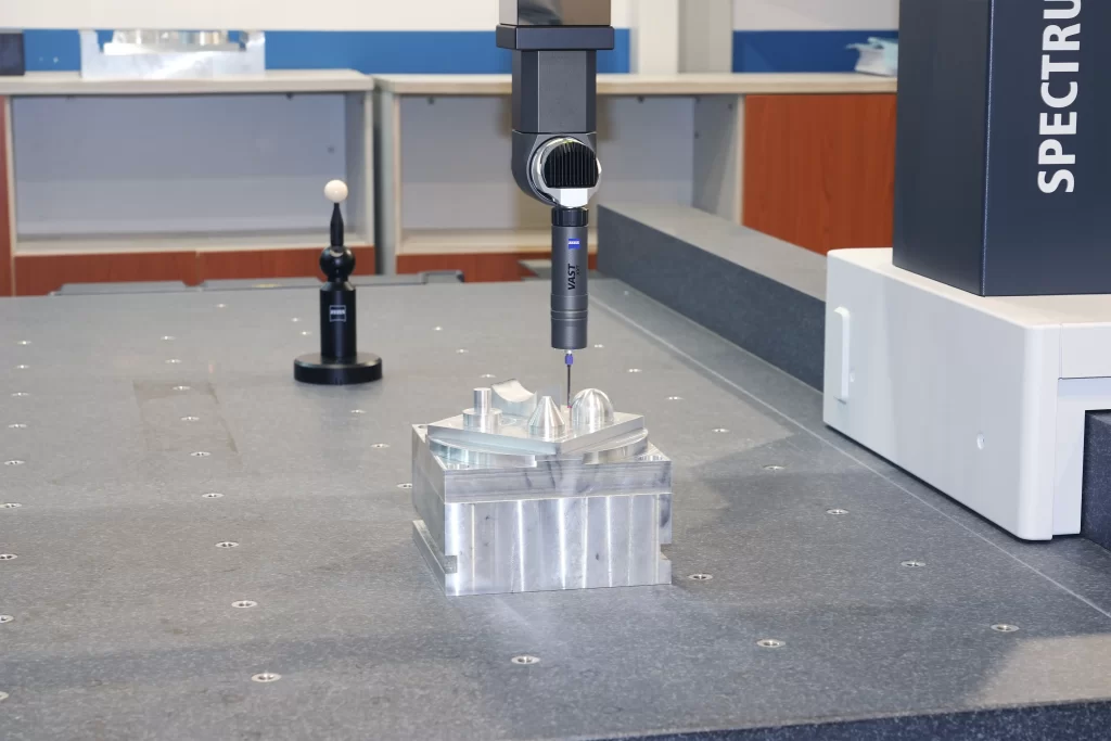
- Check dimensions with micrometers or CMM (coordinate measuring machines).
- Measure surface roughness (Ra) with profilometers, targeting Ra≤1.6 μm for finishing.
- Inspect tools regularly to catch wear early.
For aerospace parts, if Ra exceeds 1.6 μm, lower F or swap tools.
3. Continuous Improvement and Record-Keeping
Optimization is ongoing. Build a parameter database logging workpiece materials, tool types, and settings (e.g., aluminum: Vc 300 m/min, F 0.2 mm/rev). Steps:
- Track parameters, tool life, and anomalies.
- Review data quarterly to refine settings.
- Update strategies based on test cuts, like lowering Vc for sticky chips.
One shop’s database-driven tweaks cut tool changes by 20% and boosted efficiency by 15%.
Conclusion
CNC parameter optimization balances efficiency, tool life, and quality. By leveraging cutting databases, CAM simulations, adaptive controls, and tiered strategies, you can fine-tune Vc, F, and ap for robust, high-quality machining. Continuous data logging and test cuts refine the process. For example, an aerospace shop cut machining time by 15% and extended tool life by 40% through parameter tweaks. Newcomers should start with manufacturer-recommended settings and adjust through testing to match real-world conditions.