CNC Milling Machine Performance Optimization Guide
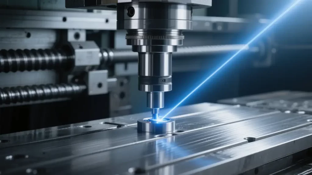
In modern manufacturing, the CNC Milling Machine is a core piece of equipment, widely applied in aerospace, mold manufacturing, automotive parts, and precision electronics. In scenarios involving complex processes such as laser beam welding, or requiring collaboration with CNC Machining Centers and CNC Vertical Machining Centers, its performance directly determines machining accuracy, surface quality, and production efficiency, which in turn affect product qualification rates and delivery cycles. In actual production, even machines of the same model can show efficiency differences of up to 30%, while tool life may fluctuate by more than 50%. This is not due to machine defects, but rather the insufficient release of system performance. This article focuses on five core systems, supported by real data and case studies, and provides quantifiable, replicable optimization strategies to help enterprises improve stability, efficiency, and cost control.
I. Key System Analysis for CNC Milling Machine Optimization
Mechanical Structure and Thermal Drift Compensation
The machine’s mechanical structure is the foundation of all cutting behavior—its rigidity and geometric accuracy are the “bones and posture” of the dancer, directly affecting machining stability.
- Spindle Runout: Excessive radial runout (>0.005 mm) leads to surface chatter, especially during high-speed cutting (>10,000 rpm). Regular balancing to ISO 1940 G0.4 ensures stability, much like a dancer maintaining perfect balance.
- Ball Screw Backlash: Over time, preload loss increases backlash (>0.01 mm), leading to “lost motion.” Laser interferometers can measure and compensate pitch error, restoring precision rhythm.
- Thermal Deformation: After 2 hours of continuous spindle operation, Z-axis thermal growth can reach 15–25 μm. Advanced systems apply Thermal Drift Compensation (TDC) via real-time sensors, like a dancer equipped with intelligent body temperature control.
- Rigidity: Machine bed materials (mineral cast vs. cast iron) and foundation stability affect modal frequency. Insufficient rigidity triggers resonance under cutting forces, degrading surface roughness—as if the stage itself shakes beneath the dancer.
CNC Control and Servo Drive Optimization
The CNC controller and servo drives are the “brain and muscles” of the machine, defining accuracy and responsiveness.
- Interpolation Accuracy: Traditional linear interpolation causes micro-pauses at corners, leaving tool marks. NURBS interpolation enables smooth, continuous motion, achieving ±1 μm path accuracy.
- Look-ahead Control: Advanced controllers pre-read 200–500 blocks to optimize acceleration profiles, avoiding abrupt starts and stops—like a dancer anticipating each move.
- Servo Gain Tuning: Improper position loop gain causes oscillation or sluggishness. Bode plot frequency analysis helps tune the “strength balance.”
- Acceleration Modes:
- Trapezoidal: abrupt and harsh.
- S-curve: continuous and smooth, ideal for precision surface machining.
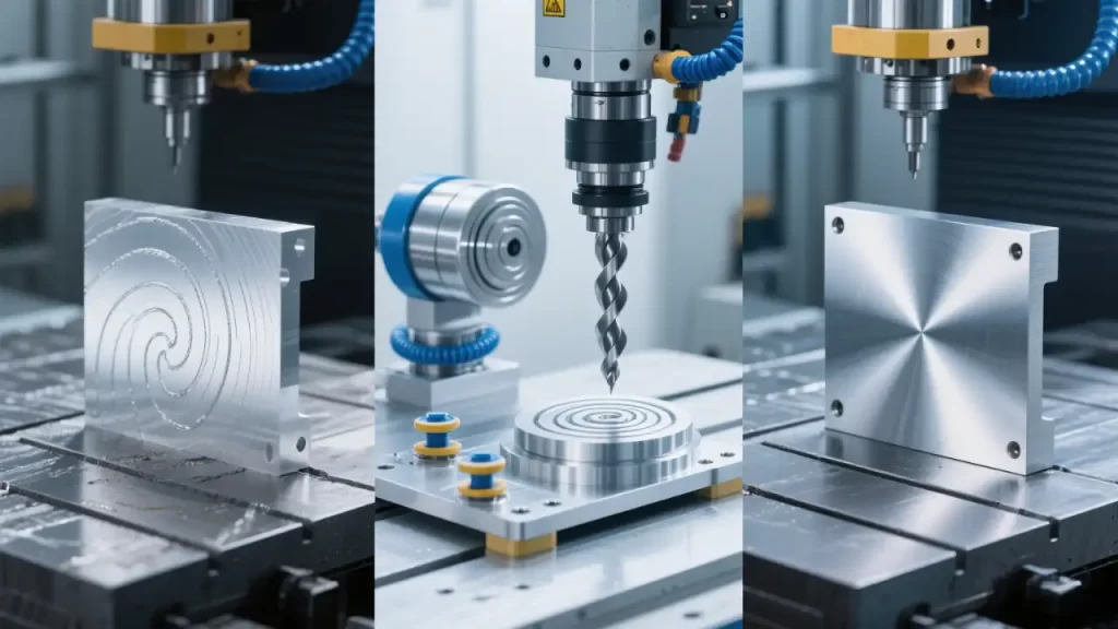
Tooling and Machining Strategy
Tools are the final executors of material removal, comparable to a dancer’s props. Tool selection and machining strategies directly shape cutting forces, heat, and tool life.
Tool Selection and Holding
| Workpiece Material | Recommended Coating | Cutting Speed (Vc, m/min) | Notes |
|---|---|---|---|
| 6061 Aluminum | PCD (Diamond) | 800–1500 | Anti-sticking, high wear resistance |
| H13 Tool Steel (52HRC) | AlTiN | 60–120 | High-temperature oxidation resistance |
| TC4 Titanium Alloy | AlCrN | 40–80 | Heat stability, anti-notch wear |
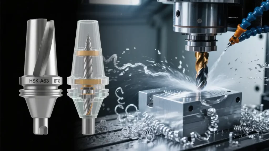
- HSK-A63 Holders: Dual contact, high rigidity, ideal for >15,000 rpm.
- BT40 Holders: Single taper contact, ~0.003 mm repeatability.
- Runout Control: ≤0.003 mm is essential to avoid premature tool wear.
Cutting Parameters and Strategies
- High Speed Milling (HSM): Shallow depth (0.1–0.5 mm), light radial engagement (10–30%), high spindle speed (8,000–20,000 rpm).
- Trochoidal Milling: Arc-entry cutting reduces cutting forces by 30–50%.
- Coolant Options:
- MQL (Minimum Quantity Lubrication): eco-friendly, <50 ml/h.
- HPC (High Pressure Coolant): ≥70 bar, effective for deep-hole machining.
Workholding and Zero-point Systems
- Zero-point System: ≤0.002 mm repeatability, setup change within 3 minutes.
- Hydraulic/Pneumatic Clamping: Consistent force, eliminating operator variability.
- Chip Removal: Chain conveyors with fine filtration maintain coolant cleanliness, prolonging tool life.
- Environment Control: Shop temperature at 20±1°C, humidity 40–60%, minimizing thermal distortion.
II. CNC Milling Optimization Strategies
Mechanical System Checklist
| Item | Procedure | Tool Used | Frequency |
|---|---|---|---|
| Guideway Lubrication | Use ISO VG 68 oil, check weekly | Visual + Oil Gauge | Weekly |
| Backlash Comp. | Measure and input correction values | Dial Gauge | Quarterly |
| Spindle Balance | Balance to G0.4, especially after tool changes | Balancer Pro | Semi-annual |
| Geometry Calibration | Check positioning, squareness, straightness | Laser Interferometer | Annual |
Control System Optimization
- Enable S-curve acceleration for smoother motion.
- Use feedforward control to minimize tracking error.
- Apply NURBS interpolation for complex surfaces.
- Keep CNC firmware updated.
- Backup parameter files after each change.
Tool Life Management and Path Planning
- Match tool material and coating to workpiece.
- Optimize cutting conditions (Vc, fz, ap).
- Choose coolant method (MQL/HPC).
- Plan efficient toolpaths (trochoidal, climb milling, layer strategies).
- Control tool runout ≤0.003 mm.
- Use TLM (Tool Life Management) to schedule tool changes.
Data-driven Monitoring and Adaptive Feed Control (AFC)
- Spindle Load: Normal 60–80% rated power; >90% triggers alarms.
- Vibration Monitoring: FFT analysis detects early bearing faults.
- Servo Alarm Logs: Track position and following errors.
- Edge Computing Terminals: Enable local AFC, adjusting feed rates in real time.
III. Case Studies
Case 1: Vibration Suppression in Aluminum Thin-wall Milling
- Surface Roughness: 3.2 μm → 1.6 μm
- Scrap Rate: 35% → 8%
- Measures: Balancing, trochoidal toolpath, vacuum clamping
- Result: Stable surfaces, 12 dB noise reduction.
Case 2: Cooling Optimization in Deep Mold Steel Cavities
- Cycle Time: 9.2 h → 6.6 h
- Tool Life: 2 h → 5 h
- Coolant: External spray → 70 bar HPC
- Result: 28% faster machining, 42% tool cost reduction.
Case 3: Tool Life Improvement in Titanium Impeller Machining
- Problem: Overheating, chipping, surface burns.
- Solution: AlCrN ball-end tools, AFC load-based speed adjustment, 80 bar HPC.
- Result: Tool life 1.5 h → 4.8 h, yield rate 96%.
IV. Implementation and Maintenance
Daily Optimization Checklist
| Item | Frequency | Notes |
|---|---|---|
| Guideway Cleaning | Weekly | Remove chips, apply special oil |
| Backlash Check | Quarterly | Laser interferometer |
| Spindle Balance | Semi-annual | After tool holder changes |
| Tool Runout Check | Each Tool Change | ≤0.003 mm |
| Parameter Backup | Each Change | Save to server archive |
Enterprise-level Continuous Improvement
- Post checklists at operator stations.
- Integrate into daily shift inspections.
- Hold monthly review meetings on efficiency and cost.
- Reward compliance and improvements to foster a strong team culture.
V. Conclusion
CNC milling machine performance optimization is a multidimensional system engineering effort, spanning mechanics, control, tooling, and data. Like a well-choreographed performance, sustainable results require coordination across all fronts. Optimization must be data-driven—spindle load curves, vibration spectra, and servo logs—not just based on experience.
By standardizing processes and preventive maintenance, manufacturers can achieve consistent improvements in quality and efficiency. If you are seeking a structured solution to boost efficiency and reduce tooling costs, we provide tailored services ranging from diagnostics and parameter tuning to real-time monitoring. Contact us for a free initial assessment and optimization proposal—so that every machine can perform at its best, just as every dancer deserves to shine on stage.