CNC Machining Materials Guide: Aluminum, Steel or Plastic
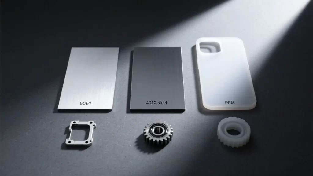
In modern precision manufacturing, CNC machining has evolved from a simple “cutting process” into a fully integrated system of material selection, machining strategy, and design optimization. Choosing the wrong material can lead to cost overruns, rework, or even mass scrap and safety incidents. This guide focuses on three major categories of CNC machining materials — aluminum alloys, steels, and engineering plastics — comparing them across six key dimensions: mechanical properties, machinability, physical traits, environmental resistance, cost structure, and application fit. Supported by decision trees, real-world case studies, troubleshooting tips, and FAQs, this guide empowers manufacturing engineers, product designers, and procurement specialists to make fast, science-backed material choices.
1. Six Core Dimensions for Material Selection
1. Mechanical Properties
- Tensile strength (MPa) defines a material’s ability to resist breaking under tension and sets the upper limit for structural loading. 6061 aluminum ≈ 310 MPa, 4140 steel ≈ 930 MPa, POM plastic ≈ 70 MPa. High-load components should prioritize high-strength steel.
- Hardness affects wear resistance and tool life — generally, steel > aluminum > plastics.
- Impact toughness determines resistance to sudden dynamic loads. Automotive crash components or moving assemblies require high-toughness materials like 4340 steel or PA6.
- Fatigue limit is the maximum cyclic stress a material can endure without failure — critical for rotating or vibrating parts (e.g., drone propellers, drive shafts).
2. Machinability
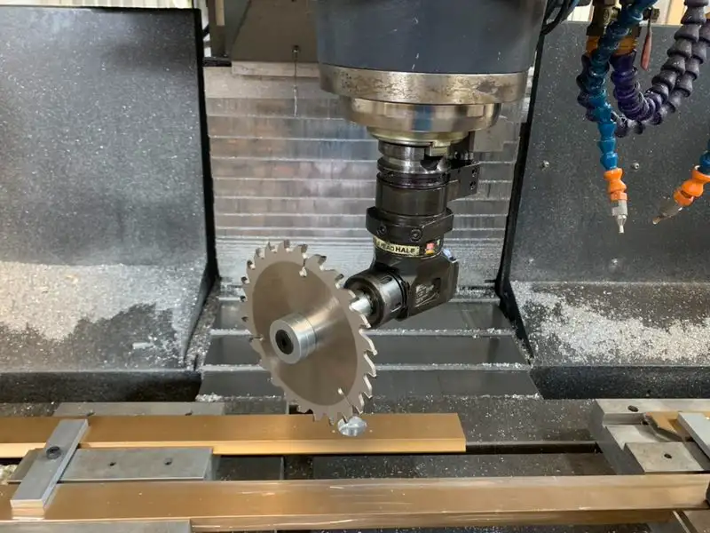
- Cutting forces for steel are 3–5× higher than aluminum, demanding more powerful machines and rigid fixturing — typically requiring CNC machines with ≥7.5 kW spindles.
- Tool wear is especially severe when machining stainless steel or titanium. TiAlN-coated carbide or CBN tools are recommended.
- Surface finish: Aluminum can achieve Ra 0.4 μm, steel Ra 0.8 μm, while plastics rarely go below Ra 1.6 μm.
- Thermal deformation is common in plastics and thin-wall aluminum parts — controlled via optimized spindle speeds and cooling strategies.
- These factors directly influence CNC programming and toolpath strategy.
3. Physical Characteristics
- Density: Aluminum = 2.7 g/cm³, steel = 7.85 g/cm³, plastics = 0.9–1.4 g/cm³. For lightweight designs, aluminum or engineering plastics are preferred.
- Thermal conductivity: Aluminum ≈ 205 W/m·K — ideal for heat dissipation components.
- Coefficient of thermal expansion: POM is as high as 105×10⁻⁶/°C — high-precision fits require dimensional compensation during design.
4. Environmental Resistance
- Corrosion resistance ranking: 316 stainless steel > anodized aluminum > carbon steel. Most engineering plastics offer good chemical resistance.
- Temperature resistance: PEEK withstands 250°C continuously; ABS softens above 80°C; 7075 aluminum begins to lose strength above 150°C.
- Aging resistance: PC yellows over time; POM is stable; metals are largely unaffected.
- Biocompatibility: For medical applications, use 316L stainless steel, PEEK, or Ti6Al4V — compliant with ISO 10993.
5. Cost Structure
| MATERIAL | RAW MATERIAL COST | MACHINING EFFICIENCY | SCRAP VALUE | POST-PROCESSING COST |
|---|---|---|---|---|
| 6061 Aluminum | Medium | High | High | Medium |
| 45# Steel | Low | Medium | Medium | Low |
| PEEK Plastic | Very High | Low | Low | High |
→ Aluminum offers the best overall value. PEEK is only recommended for extreme-temperature or medical applications.
6. Application Fit
- Structural load-bearing parts → 7075 aluminum, 4140 steel
- Decorative/aesthetic parts → 6061 aluminum + anodizing, transparent PC
- Wear-resistant sliding parts → POM, PA66+GF30
- Insulating/sealing parts → PTFE, PEEK
- Heat dissipation components → 6061/1060 aluminum, copper alloys
Designers should collaborate early with CNC machinists to optimize features, fixturing, and machining allowances — avoiding costly late-stage changes.
2. Aluminum Alloys: The Lightweight Champion
Common Alloy Comparison
| ALLOY | TENSILE STRENGTH (MPA) | TYPICAL APPLICATIONS | MACHINING TIPS |
|---|---|---|---|
| 6061 | 310 | Housings, brackets, consumer electronics | Easy to machine; accepts anodizing and coloring |
| 7075 | 572 | Aerospace structures, drone arms | High strength but prone to built-up edge |
| 5052 | 228 | Fuel tanks, marine parts, corrosive environments | Excellent weldability; ideal for wet environments |
Key Advantages in CNC Machining
- High cutting speeds (800–2000 m/min) — compatible with 5-axis machining centers and CNC mills. Optimal range: 1000–1800 m/min for balancing efficiency and surface quality.
- Low cutting forces — reduces machine load, ideal for thin-wall or small-format parts.
- Excellent surface finish — diamond tooling can achieve Ra 0.2 μm, meeting premium cosmetic standards.
- Superior heat dissipation — minimizes thermal distortion during machining.
Limitations & Mitigation Strategies
- Limited strength ceiling — not suitable for heavy-load gears or spindles; consider alloy steel instead.
- Prone to built-up edge and chip adhesion — use sharp-edged tools with high-pressure emulsion coolant (8–12% concentration).
- Burr control is challenging, especially around through-holes and contours — always include deburring steps (thermal, tumbling, or manual).
- Anisotropy in rolled sheet: longitudinal strength is 10–15% higher than transverse — specify grain direction alignment for high-stress features.
Typical Applications
- Smartphone mid-frames, laptop enclosures (6061-T6)
- Drone arms, RC aircraft structures (7075-T6) — requires 5-axis simultaneous machining
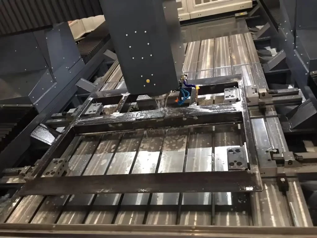
- EV battery trays (6061/5083) — machined on large gantry mills
3. Steels: The Foundation of Strength and Precision
Common Types & Applications
- Carbon Steels:
- A36/Q235: Frames, non-critical structures — excellent weldability
- 45# Steel (C45/1045): Shafts, gear blanks — hardened to HRC 28–32 after quench & temper
- Alloy Steels:
- 4140 (42CrMo): High-stress shafts, connecting rods — tensile strength ≥930 MPa
- 4340 (40CrNiMo): Aircraft landing gear, racing drivetrains — superior toughness
- Stainless Steels:
- 304 (SUS304): General corrosion resistance — food & chemical equipment (difficult to machine)
- 316 (SUS316): Molybdenum-enhanced — resists acids, saltwater; preferred for medical devices
- 17-4PH (630): Precipitation-hardening — reaches HRC 44; ideal for aerospace fasteners and valve bodies
Machining Challenges & Solutions
- High cutting forces — requires ≥7.5 kW spindle power; best suited for heavy-duty CNC lathes or vertical machining centers.
- Pronounced work hardening (especially 304/316):
- Use PVD-coated tools (e.g., TiAlN)
- Apply “low speed, high feed” strategy (Vc=60–120 m/min, f=0.2–0.4 mm/rev)
- Avoid tool dwell — prevents hardened layer buildup
- Coordinate with your machine shop for automation-compatible strategies
- Demands high-pressure coolant — use extreme-pressure emulsion (10–15% concentration, ≥30 bar pressure)
- Chip breaking is difficult — use chip-breaker inserts or high-pressure through-tool coolant
Typical Applications & Post-Processing
- Injection mold bases (45# steel) — rough machined → quench & temper → precision ground
- Surgical instruments (316L) — surface finish ≤Ra 0.8 μm — requires EDM or surface grinding + passivation
- Food processing valves (316) — must withstand steam sterilization; avoid copper-containing alloys
4. Engineering Plastics: Functional Integration & Lightweighting
Material Properties Quick Reference
| Material | Tensile Strength (MPa) | Max Continuous Temp | Friction Coeff. | Water Absorp. | Typical Applications |
|---|---|---|---|---|---|
| ABS | 40 | 80°C | 0.3–0.5 | 0.3% | Enclosures, prototyping |
| POM | 70 | 100°C | 0.1–0.3 | 0.2% | Gears, bearings, sliders |
| PA6 | 80 | 120°C | 0.2–0.4 | 3.0% | Requires dimensional compensation after moisture absorption |
| PEEK | 100 | 250°C | 0.3–0.4 | 0.1% | Medical, semiconductor, aerospace |
CNC Machining Best Practices
- Tool Selection:
- Glass-fiber reinforced plastics (e.g., PA66+GF30) require PCD (polycrystalline diamond) tools
- Avoid coated tools — risk of chemical adhesion with plastics
- Cooling Methods:
- Prefer compressed air — especially for PTFE (never use water-based coolants)
- Light oil mist acceptable — prevents swelling or warping
- Workholding:
- Use vacuum chucks or polyurethane soft jaws
- For thin-wall parts, support with low-melting-point alloy or wax filling
- Post-Machining Treatment (Essential):
- POM: Anneal at 150°C × 2 hrs, furnace-cooled slowly
- PEEK: Anneal at 200°C × 4 hrs
- Never quench — risk of stress cracking
Design Pitfalls & Optimization Tips
- Sharp corners cause stress concentration — add fillets (R ≥ 0.5 mm)
- Thin ribs (<1 mm) induce chatter — thicken or add stiffeners
- Deep holes (L/D > 5) cause tool deflection — machine in stages or switch to wire EDM
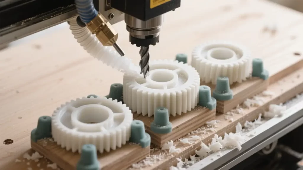
- Complex contours — best handled by CNC routers or 5-axis machining centers
Typical Applications
- Self-lubricating gears/sliders (POM) — maintenance-free, quiet operation
- Semiconductor wafer handlers (PEEK + carbon fiber) — heat-resistant + ESD-safe; requires micro-machining centers
- FDA-compliant food-contact parts (POM/PTFE) — plasticizer-free, steam-sterilizable
5. Quick Comparison Table: Aluminum vs. Steel vs. Plastics
| EVALUATION CRITERIA | ALUMINUM (6061-T6) | STEEL (4140, Q&T) | PLASTIC (POM) |
|---|---|---|---|
| Density (g/cm³) | 2.7 | 7.85 | 1.42 |
| Tensile Strength (MPa) | 310 | 930 | 70 |
| Recommended Cutting Speed | 1000–1800 m/min | 80–150 m/min | 800–1500 m/min |
| Surface Roughness Ra | 0.4–0.8 μm | 0.8–1.6 μm | 1.6–3.2 μm |
| Corrosion Resistance | Medium (high after anodizing) | Low (high for stainless) | High |
| Cost Index (1–10) | 4 | 6 | 3 (PEEK = 9) |
| Primary Compatible Equipment | 5-axis machining center | CNC lathe | CNC router |
6. Material Selection Decision Tree + Real-World Case Studies
Quick Decision Flow for Engineers
- Need tensile strength > 500 MPa? → Choose steel (4140 / 17-4PH)
- Need lightweight or heat dissipation? → Choose aluminum (6061 / 7075)
- Need electrical insulation, self-lubrication, or chemical resistance? → Choose plastic (POM / PEEK)
- Budget-sensitive? → Choose A36 steel / 6061 aluminum / ABS
- Extreme environment (>200°C / strong corrosion)? → Choose 17-4PH / 316 / PEEK
Case Study Breakdowns
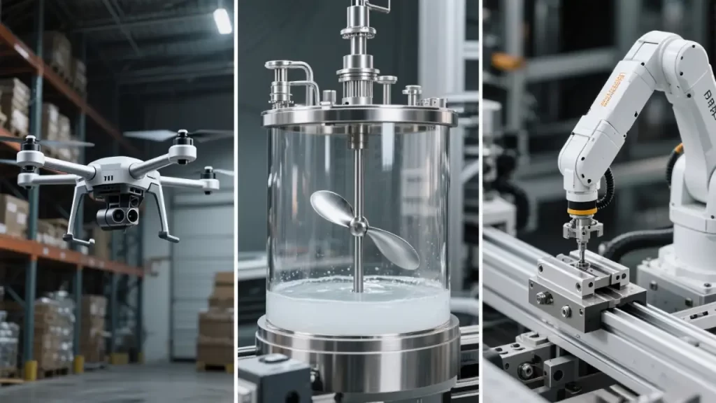
Industrial Drone Arm — Material: 7075-T6 Aluminum
- Requirements: Lightweight (<200g), high flexural strength (>400 MPa), weather resistance
- Machining Notes: 5-axis single-setup machining; optimize toolpaths to prevent chatter; include deburring step
Bioreactor Agitator Shaft — Material: 316L Stainless Steel
- Requirements: Steam sterilizable (120°C), acid/alkali resistant, surface finish ≤Ra 0.8 μm
- Machining Notes: Slow finish milling + passivation; avoid intergranular corrosion; EDM finishing recommended
Automation Linear Slider — Material: POM
- Requirements: Low friction (μ<0.2), lubrication-free, dimensional stability
- Machining Notes: Anneal after machining; design with 0.1% shrinkage allowance; use CNC router for efficiency
Semiconductor Wafer Handler — Material: PEEK + Carbon Fiber
- Requirements: 200°C resistance, high purity, electrostatic dissipation
- Machining Notes: Use PCD tools only; avoid sulfur-containing coolants; micro-machining center for precision
7. Frequently Asked Questions (FAQ)
Q1: Why did my 6061 aluminum support bracket fracture under load?
A: 6061-T6 has a tensile strength of ~310 MPa. Failure often occurs due to exceeding design stress limits or ignoring “anisotropy” in rolled sheet — longitudinal strength is 10–15% higher than transverse.
Recommendations: ① Switch to 7075-T6 (572 MPa); ② Specify “grain direction parallel to primary load”; ③ Confirm clamping and toolpath alignment with your machinist.
Q2: Why do my tools keep chipping or wearing out fast when machining 304 stainless?
A: 304 is an austenitic stainless steel with strong work-hardening tendency.
Solutions: ① Use TiAlN-coated carbide inserts; ② Apply low-speed, high-feed strategy (Vc=60–100 m/min, f=0.3 mm/rev); ③ Avoid stopping mid-cut — prevents hardened layer buildup; ④ Use high-pressure through-tool coolant (≥30 bar); ⑤ Consider switching to free-machining 303 stainless.
Q3: Why do my POM parts slowly deform after CNC machining and assembly?
A: This is caused by residual stress + moisture absorption — leading to dimensional drift.
Mandatory steps: ① Anneal immediately after machining (150°C × 2 hrs, slow cool); ② Design in 0.1–0.3% shrinkage allowance; ③ Store finished parts in controlled environment (RH < 50%); ④ Avoid water-based coolants during machining.
Q4: What’s the most cost-effective way to produce high-aesthetic CNC parts?
A: Use 6061-T6 aluminum + anodizing (available in black, gold, blue, etc.).
Advantages: ① Moderate material cost; ② Easy to machine on standard CNC mills or 5-axis centers; ③ Supports premium finishes — brushing, bead blasting, laser engraving; ④ 100% recyclable — eco-friendly and cost-efficient.
Q5: PEEK is too expensive — are there practical alternatives?
A: Depends on your operating environment:
→ Temp < 150°C + insulation needed → Use PPS (~1/3 cost of PEEK, 80 MPa strength) → Temp < 100°C + self-lubrication → Use POM or PA66+30%GF (cost ~1/10 of PEEK) → High temp + wear resistance → Consider PI (polyimide) or metal with coating
Q6: How do I prevent severe deformation when machining thin-wall aluminum (0.5mm thickness)?
A: Deformation stems from thermal buildup and clamping stress.
Solutions: ① Use small-diameter, sharp tools (φ2–φ4mm); ② High speed, low feed (Vc=1500–1800 m/min, f=0.03–0.05 mm/rev); ③ Direct high-pressure coolant at cutting zone; ④ Use vacuum chuck + low-melting-point alloy support; ⑤ Rough and finish in separate operations — leave 0.1mm for final pass.
Q7: When should I use a 3-axis machine vs. a 5-axis machining center?
A: Rule of thumb:
→ Use 3-axis mills/lathes for: flat features, rotational parts, hole patterns, simple contours (e.g., flanges, shafts, boxes) → Require 5-axis for: complex 3D surfaces, multi-sided machining, deep cavities, high-precision angular features (e.g., impellers, drone arms, medical implants) → Pro tip: Involve your CNC programmer during design reviews — prevents “unmachinable” geometries.
8. Conclusion: There’s No “Best” Material — Only the “Right Fit”
Material selection is fundamentally about balancing performance, cost, manufacturability, lead time, and risk of failure. We recommend:
- Build an internal CNC Machining Materials Knowledge Base
- Implement DFM (Design for Manufacturing) workflows — involve machinists early in design
- Explore hybrid processes (e.g., 3D printing + CNC finishing)
- Schedule regular training on CNC programming and cutting tool technology
Whether you’re running an entry-level CNC mill or an industrial 5-axis machining center — smart material choices + optimized processes = first-time-right manufacturing, cost reduction, and efficiency gains.