CNC Machining Center Automation: How Tool Magazines & ATC Systems Boost Productivity
1. The Foundation of CNC Machining Center Automation
1.1 Core Capabilities and Automation Hierarchy
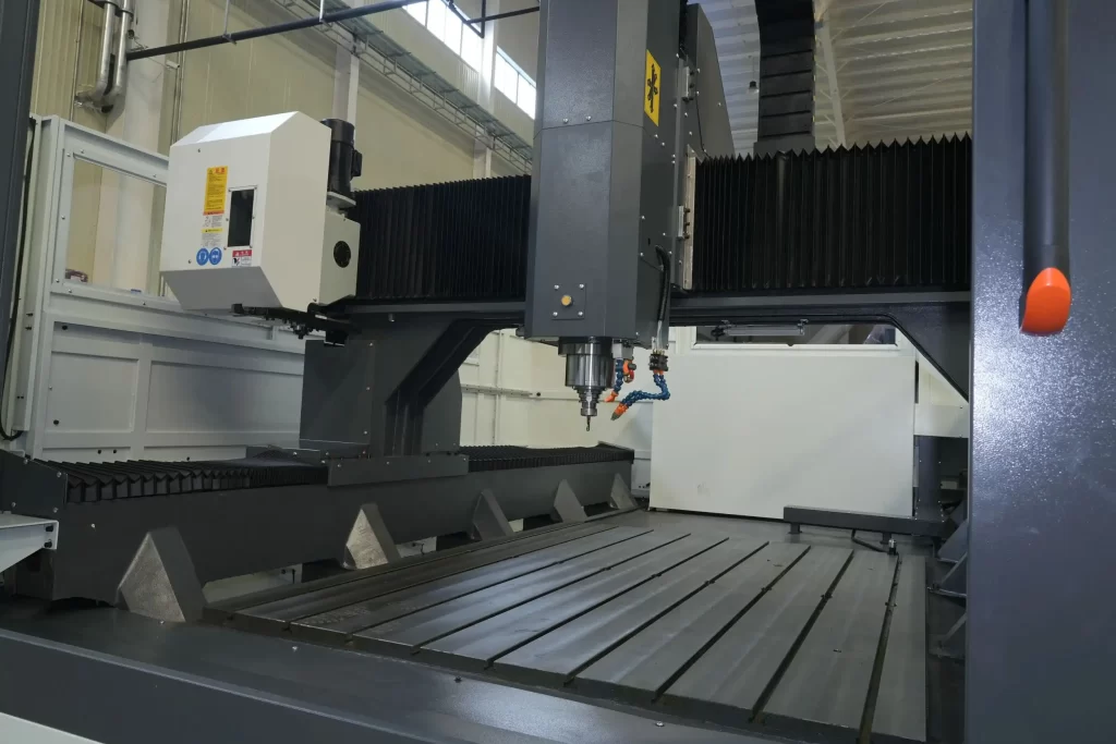
A CNC machining center is a high-precision metal-cutting machine equipped with a spindle system, multi-axis motion, numerical control, and crucially—a tool magazine and automatic tool changer (ATC). These features allow it to perform milling, drilling, tapping, boring, and other operations in a single setup, minimizing manual intervention and non-cutting time.
Unlike standard CNC machines, machining centers are designed for continuous multi-operation processing, making them indispensable in industries such as aerospace, automotive, mold making, and precision manufacturing. Depending on their configuration, they come in vertical, horizontal, gantry, and 5-axis versions—each optimized for specific workpiece geometries and production needs.
Modern CNC machining centers feature a three-tiered automation architecture:
- Tool-Level Automation: Centered on the ATC, enabling fast and precise tool changes. Key performance indicators include tool-to-tool (T-to-T) change time, repeatability (≤±0.005 mm), and reliability (mean time between failures > 10,000 cycles).
- Workpiece-Level Automation: Achieved via automatic pallet changers (APC) or robotic loading/unloading systems. A typical APC swaps pallets in 30–90 seconds, supporting dual or multi-pallet operations to drastically reduce idle time.
- Cell-Level Integration: Multiple machines, tool management systems (TMS), and material handling units (e.g., RGVs, AGVs) are integrated into Flexible Manufacturing Cells (FMCs) or Systems (FMS), enabling lights-out, continuous production.
1.2 Impact of Tool Change Time on Cycle Efficiency
In typical box-type part machining, non-cutting time accounts for 40%–60% of the total cycle, with tool changes alone consuming 15%–30%. For example, a program using 18 tools across 12 operations with a 4-second average tool change results in 72 seconds of cumulative tooling time. By switching to a high-speed chain magazine that reduces T-to-T time to 2.8 seconds, this drops to 50.4 seconds—a saving of 21.6 seconds, boosting overall efficiency by 7%–10%.
Moreover, frequent tool changes increase spindle wear. Each tool change requires the spindle to re-accelerate to operating speed, consuming 1.3 to 1.5 times more energy than steady-state operation. Therefore, optimizing tool change strategies not only improves throughput but also extends spindle life and reduces energy costs.
1.3 Indirect Effects of Automatic Tool Changing on Machining Accuracy
While tool changing doesn’t directly cut metal, mechanical disturbances during the process can accumulate and compromise final accuracy. Key sources of error include:
- Spindle Orientation Error: Before a tool change, the spindle must align precisely (typically vertically). Deviations beyond ±0.1° can misalign the tool holder keyway, causing eccentric mounting.
- Inconsistent Drawbar Force: Fatigued disc springs or fluctuating hydraulic pressure can cause drawbar force variation exceeding ±5% (standard: ~10,000 N), leading to axial tool float and inconsistent hole depth.
- Taper Surface Contamination: Coolant, chips, or oil on HSK or BT tapers reduce contact stiffness. Tests show contamination can increase runout by 0.01–0.03 mm, directly affecting surface finish and dimensional accuracy.
Thus, the stability of the ATC is not just about speed—it’s a foundational requirement for precision machining.
2. Tool Magazine Design and Engineering Implementation
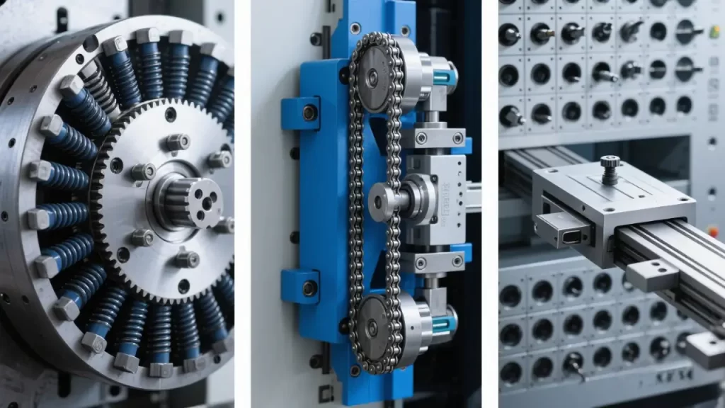
2.1 Drum (Carousel) Magazine: Compact and Responsive
Drum magazines are compact and fast, making them ideal for small to mid-sized vertical machining centers. Typical capacity ranges from 16 to 30 tools—perfect for stable, repetitive production.
Indexing Mechanisms
- Face Cam (End Tooth Plate): Uses a multi-tooth engagement (e.g., 60 teeth) for indexing accuracy of ±2 arcseconds and repeatability ≤±3 arcseconds. Locked hydraulically or pneumatically for rigidity.
- Positioning Pin + Encoder Feedback: Driven by servo motors and worm gears with closed-loop encoder control. Slightly slower than face cams but allows random access to any tool, offering greater flexibility.
Drive Systems
- Servo Motor + Worm Gear: High torque and self-locking—ideal for heavier loads. Typical reduction ratios: 60:1 to 100:1, motor power: 0.4–0.75 kW.
- Stepper Motor + Cam Indexer: Lower cost, but limited dynamic response. Best suited for low-speed, light-duty applications.
Tool Holder Clamping
Each tool pocket includes a spring-loaded retention mechanism:
- Spring Clamp (Retaining Claw): Uses disc springs to prevent tool ejection during high-speed rotation. Clamping force: 80–120 N.
- Axial Stop Nut: Adjustable to ensure consistent Z-axis reference across all tools, with positioning error held within ±0.02 mm.
Tool Orientation in Magazine
Tools are typically tilted 5°–7° in the magazine to align the flange with the arm’s gripper. This tilt minimizes impact during tool pickup and ensures smooth engagement.
2.2 Chain Magazine: Scalable and High-Capacity
Chain magazines suit medium to large machining centers, offering 30–120+ tool capacity—ideal for complex, multi-step jobs.
Chain Selection
- Double-Pitch Roller Chain: Pitch 12.7 mm or 15.875 mm, tensile strength ≥80 kN—ideal for heavy-duty, high-capacity use.
- Short-Pitch Precision Chain: 9.525 mm pitch, smoother operation, noise <70 dB(A)—preferred in noise-sensitive environments.
Tensioning Mechanisms
Chains stretch over time and require tension control:
- Eccentric Sprocket: Manual adjustment—requires frequent maintenance.
- Pneumatic Tensioner: Applies constant pressure (0.3–0.5 MPa) to compensate for elongation.
- Automatic Compensation: Uses displacement sensors to trigger tensioning when chain stretch exceeds 1.5 mm.
Tool Position Encoding
- Absolute Encoder: Each tool has a unique address—no homing needed, fixed search time.
- Incremental (Pulse Counting): Relies on pulse tracking; requires homing at startup and risks position loss if steps are missed.
Multi-Level Chain Magazine: Smart Addressing
For double- or multi-tier designs, a two-stage addressing strategy is used: coarse positioning (move entire chain to target tier), followed by fine indexing (locate exact tool). This keeps average tool search time under 2.5 seconds.
Application Insight: Chain magazines are widely used in CNC milling machines and horizontal machining centers, especially for complex, high-mix production.
2.3 Matrix Magazine: High-Density 2D Storage
Matrix (grid-style) magazines use X-Y coordinate positioning for high-density storage—common configurations are 8×8 or 10×10, supporting over 100 tools.
X-Y Positioning Platform
Dual servo linear modules provide motion: X-axis travel 300–600 mm, Y-axis 150–300 mm. Repeatability must be ≤±0.05 mm, achieved via ball guides and C3-grade precision ball screws.
Insertion Force Control
Inserting tools into grid slots generates friction. Tapered guides and linear bearings help keep insertion force between 30–50 N, preventing holder deformation.
Safety Interlocks
- Safety Light Curtains: Prevent human access during operation.
- Limit Switches: Confirm magazine door closure before movement.
- Emergency Stop Integration: Triggers immediate servo brake engagement.
2.4 Integration with Machine Enclosure and Protection
These sealing strategies are common in high-protection-grade vertical CNC machining centers, shielding internal components from coolant and debris.
Dust and Chip Sealing
- Brush Seals: Installed at rotating joints to block large chips.
- Labyrinth Seals: Use complex pathways to prevent coolant ingress into bearings.
Coolant Isolation
- Flexible Curtains: Rubber or plastic flaps cover the magazine opening, retracting only during tool change.
- Drip Pans: Positioned beneath the magazine to collect coolant, directing it to the chip conveyor.
Thermal Management
Continuous motor operation generates heat. When ambient temperatures exceed 35°C, small fans or forced-air cooling systems maintain internal temperature rise within 15K.
3. Automatic Tool Changer (ATC): Motion Sequence and Control Logic
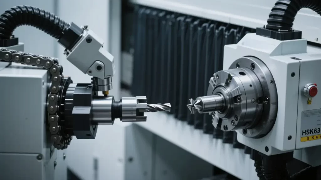
3.1 Typical Cam-Driven Arm Tool Change Process
Using a common dual-arm cam-driven tool changer, the process unfolds in six tightly controlled phases:
- Spindle Orientation: CNC issues M19 command. The spindle rotates to a preset angle (e.g., 0° or 90°), verified by encoder (error ≤±0.1°).
- Spindle Release: Solenoid valve activates, sending compressed air (0.5–0.7 MPa) to drive the knock-out cylinder down 8–12 mm, releasing the tool holder. Completion confirmed by pressure or position sensor.
- Arm Rotation: Servo or cam mechanism rotates the arm 180°, moving one arm toward the spindle, the other to the magazine.
- Simultaneous Pick & Place: Grippers on both arms engage the used tool (on spindle) and new tool (in magazine), swapping them in one motion. Gripping force: 60–80 N, set via spring preload or pneumatic control.
- Spindle Clamp: Knock-out cylinder retracts; disc springs or hydraulic system apply 8,000–15,000 N drawbar force to secure the new tool. Completion confirmed via motor current or pressure feedback.
- Arm Return: Arm rotates back to standby position. Spindle orientation is released, and cutting resumes.
Each step is executed by the PLC with interlocks—any failure halts the sequence.
3.2 Signal Feedback and Closed-Loop Control
- Tool Release Confirmation: Pneumatic logic valves or pressure sensors verify full cylinder extension.
- Drawbar Force Monitoring: Indirectly measured via spindle motor current—typically increases 15%–20% during clamping.
- Arm Position Feedback: Rotary encoder tracks arm angle; deviation >±1° triggers alarm.
- Safety Interlock: During tool change, X/Y/Z axes are disabled to prevent interference.
3.3 Tool Change Time Comparison (Measured Data)
| MAGAZINE TYPE | TOOL CHANGE METHOD | AVG. T-TO-T TIME (SEC) | NOTES |
|---|---|---|---|
| Drum | Cam-Driven Arm | 2.5–4.0 | Includes spindle orientation |
| Chain | Servo Arm | 3.5–6.0 | Includes tool search time |
| Matrix | Cartesian Robot | 5.0–8.0 | X-Y positioning adds delay |
| Direct Change | No Arm (Adjacent Only) | 1.8–2.5 | Limited to adjacent tool slots |
Note: T-to-T (Tool-to-Tool) time measures the interval from one tool finishing cutting to the next starting.
3.4 Specialized Tool Change Modes
- Skip Tool Change: System bypasses empty tool positions. E.g., when calling T05, skips over T03 if empty.
- Mirror Tool Change: Arm rotates in reverse to avoid spatial interference—requires pre-defined clearance angles.
- Mandatory Tool Change: Forces tool replacement upon tool life expiration or breakage detection, even mid-operation.
4. Tool Management System (TMS): Engineering Integration
4.1 Tool Identification Technologies
- Binary Code Ring: 8-bit gray code ring on tool flange, read by photoelectric sensors—supports up to 256 tools, prevents misreads during transitions.
- RFID Tags: Embedded in tool holders, storing tool type, diameter, length, and life data. Read range: 5–10 cm; resistant to oil and debris.
- QR Code Scanning: Laser or vision system reads engraved QR codes on holders—accuracy ≥99.5%.
4.2 Tool Data Flow
- Tools are preset on a tool presetter; L (length) and D (radius) offset values are recorded.
- Data is transferred via USB, RS232, or network to the CNC.
- DNC server synchronizes a central tool database across multiple machines.
- When the program calls a T-code, the corresponding H/D offset is automatically loaded.
4.3 Tool Life Management
- Time-Based: Tracks spindle running time (minutes). E.g., a milling cutter rated for 60 minutes accumulates runtime per minute.
- Count-Based: Tracks number of parts or feed distance (mm)—ideal for high-volume production.
- Load-Adaptive Algorithm: Adjusts wear rate based on real-time spindle power:Consumption Rate = Base Rate × (P_actual / P_rated)¹·⁵ Where P_actual is measured power, P_rated is nominal cutting power.
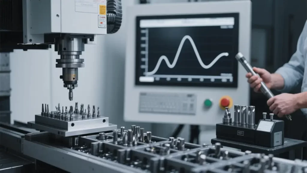
4.4 Tool Breakage Detection
- Acoustic Emission (AE) Sensors: Mounted on spindle housing, detect high-frequency vibrations (100 kHz–1 MHz). A 50%+ spike indicates chipping or fracture.
- Spindle Power Monitoring: A sudden 30%+ drop in cutting power suggests tool failure.
- Air Blow Test: After tool change, 0.5 sec of compressed air is blown through the spindle. Lack of airflow (due to missing tool) triggers an alarm.
5. Mechanical Interfaces and Coordinated Control
5.1 ATC and Spindle Interface Precision
- Spindle Keyway: Width tolerance H7/f7 (+0.018/0 mm), depth ±0.02 mm.
- Taper Contact Area: Red dye test—BT40 ≥85%, HSK63 ≥90%.
- Pull Stud Torque: BT holders: 12–15 N·m; HSK: 25–30 N·m (applied with calibrated torque wrench).
5.2 Vibration Suppression During Tool Change
- Arm Balance: Mass difference between arms ≤50 g to prevent rotational imbalance.
- Cam Profile Optimization: Modified sine or trapezoidal motion curves reduce jerk and impact.
- Axis Locking: PLC disables X/Y/Z servo drives during tool change to isolate the spindle.
5.3 Coordination with Automatic Pallet Changers (APC)
- Parallel Sequencing: While the spindle is cutting, the APC unloads the finished part and loads the next—overlapping non-cutting operations.
- Zone Interlocks: Define three exclusive zones—machining, tool change, and pallet change—preventing simultaneous access.
5.4 Robot Loading and ATC Timing Synchronization
- If robot loading takes 45 sec and machining + tool changes take 50 sec, seamless flow is possible.
- If machining is faster, consider dual-station robots or dual-spindle machines to balance throughput.
6. Common Failure Modes and Field Commissioning Tips
6.1 Typical ATC Faults
| SYMPTOM | LIKELY CAUSE | SOLUTION |
|---|---|---|
| Tool Jam | Bent holder, loose pull stud, insufficient knock-out stroke | Replace holder, tighten stud, adjust air pressure |
| Tool Drop | Worn gripper, weak clamping force | Replace springs, recalibrate air pressure |
| Post-Change Vibration | Contaminated taper, failed drawbar | Clean taper, inspect disc springs |
6.2 Magazine Position Calibration
- Mount a dial indicator on the spindle, touch it to a tool holder bore, and rotate the magazine manually.
- If runout exceeds 0.02 mm, adjust indexing pins or re-zero the encoder.
6.3 Arm Synchronization Check
- Use feeler gauges to measure height difference between grippers—max deviation: 0.1 mm.
- If misaligned, inspect cam groove wear; replace if necessary.
6.4 Pneumatic System Maintenance
- Knock-Out Pressure: 0.5–0.7 MPa; below 0.4 MPa risks incomplete release.
- Oil Mist Lubricator: 5–8 drops per minute—excess oil contaminates tool tapers.
7. Advanced Engineering Solutions for Demanding Applications
7.1 Tilted Tool Changes in 5-Axis Machines
In 5-axis machining, the spindle often tilts (e.g., B-axis at 30°), making vertical tool changes impossible. Solutions:
- Program a dedicated tool change position (e.g., G-code returns spindle to vertical).
- Extend the tool magazine and arm to accommodate tilted spindle positions.
Tip: This design is common in 5-axis CNC machines and large CNC machining centers, demanding higher precision in tool alignment.
7.2 Handling Extra-Long Tools (>300 mm)
- Increase magazine height to accommodate long tools.
- Add support rails on the arm to prevent sagging and jamming.
7.3 Special Handling for HSK Tooling
- Automatically blow out HSK hollow taper before and after tool change to remove chips.
- Arm gripping angle must be precise (±0.5°) to ensure proper engagement of asymmetric keys.
7.4 Shared Tool Magazine in Multi-Spindle Machines
- Use round-robin scheduling to prevent both spindles from requesting the same tool simultaneously.
- Share tool status via shared memory for real-time consistency.
8. Automation Differences: Metal vs. Wood CNC Machining
While control principles are similar, metal CNC machines and woodworking CNC routers differ significantly in automation design due to load, tool usage, and environment.
8.1 Load and Structural Rigidity
- Metal CNC Machines: Built on heavy cast iron beds, spindles from 7.5–50 kW, cutting forces up to 8,000 N—require robust, rigid ATCs and magazines.
- Wood CNC Routers: Lower power (3–15 kW), lighter loads—allow lighter chain or drum magazines; some even use manual tool changes.
8.2 Tool Change Frequency and Capacity
- Metal parts often require 8–20 tool changes per piece—hence, 30+ tool capacity is standard.
- Woodworking focuses on profiling and engraving—fewer tool types (e.g., flat, ball-nose, V-bit). Some CNC wood routers use 6–12 tool magazines or manual changes.
8.3 Worktable Design and Material Handling
- Wood CNC Router Tables: Often use T-slots or vacuum tables for sheet material. Vacuum lines must shut off during tool changes to prevent debris suction.
- High-end CNC carving machines use automatic locating pins for repeatable multi-zone carving (±0.02 mm repeatability).
- Benchtop CNC Mills integrate coolant channels and chip conveyors; some include 4th-axis rotary tables for 5-axis capability.
8.4 Environmental Adaptation and Protection
- Metal machining produces coolant mist and metal chips—magazines require IP54+ protection, labyrinth seals, and drip trays.
- Woodworking generates fine dust—requires high-volume dust extraction; many CNC wood cutters integrate central dust collection.
Note: While CNC plasma and laser cutters aren’t traditional machining centers, they use G-code programming and some high-end models support auto-tooling and real-time data transfer.
9. From Machine to Factory: CNC Machining Services in Practice
The technologies discussed—tool magazines, ATCs, automation—are not just features of individual machines. They form the backbone of modern CNC machining service providers.
A typical CNC machining facility today includes:
- Multiple vertical/horizontal machining centers in FMCs
- Robot-loaded, unmanned workcells with chain magazines
- Centralized TMS managing hundreds of tools
- Hybrid lines handling both metal and wood CNC processing (e.g., furniture with metal fittings)
Fluency in CNC G-code and M-code is essential for programmers, directly impacting tool change logic and cycle efficiency.
In the end, it’s not just about the machine—it’s about how smart automation transforms precision into productivity.