Can a Milling Machine Be Used as a Drill Press
1. Defining the Roles: Milling Machines vs. Drill Presses
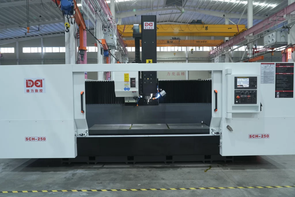
In modern metal-cutting operations, milling machine operation and drill press usage represent two fundamental, yet distinct, machining processes. Drill presses are engineered specifically for efficient, high-thrust axial drilling. In contrast, vertical milling machines are designed as versatile platforms capable of complex multi-axis contouring, slotting, facing, and — crucially — precision holemaking.
A frequently debated question on the shop floor is: Can you use a milling machine as a drill press? While both machines can physically hold a drill bit and plunge axially, a deeper analysis of milling machine rigidity, positional accuracy, spindle dynamics, and safety reveals a significant gap between “possible” and “practical.” This document provides an engineering-grade evaluation of when, how, and under what constraints milling machines can — or should not — be used for drilling operations.
2. Structural and Functional Comparison: Milling Machines vs. Drill Presses
2.1 Core Design Philosophies
| Feature | Drill Press | Milling Machine |
|---|---|---|
| Primary Function | Dedicated to axial drilling, reaming, and tapping. Optimized for speed and simplicity in repetitive holemaking. | Multi-functional platform supporting milling, drilling, boring, tapping, and contouring in a single setup. |
| Spindle Rigidity | Extremely high. Short overhang (< 100 mm) maximizes resistance to axial thrust — often rated for 5–15 kN depending on model. | Moderate to high. Spindle overhang (typically 150–300 mm) reduces axial stiffness.Milling machine rigidityis adequate for precision work but not heavy-duty production drilling. |
| Positioning Accuracy | ± 0.1 mm (manual), suitable for general-purpose holes. | ± 0.02 to ± 0.05 mm (CNC withdigital readout for milling machine), ideal for holes requiring tight positional tolerance relative to milled features. |
| Tool Compatibility | Limited to drills, reamers, counterbores, and taps. | Broad — accepts end mills, face mills, drills, boring heads, and more (tooling for milling machine). |
| Drilling Efficiency | Fast — optimized for single-purpose, high-volume drilling. | Moderate — includes time for tool changes, workpiece setup, and coordinate positioning (how to set up a drill bit in a milling machine colletadds setup time). |
Note: Data based on common mid-size industrial equipment. Actual performance varies by machine class, spindle power, and fixturing.
3. Technical Feasibility of Drilling on Milling Machines
3.1 Toolholding and Setup
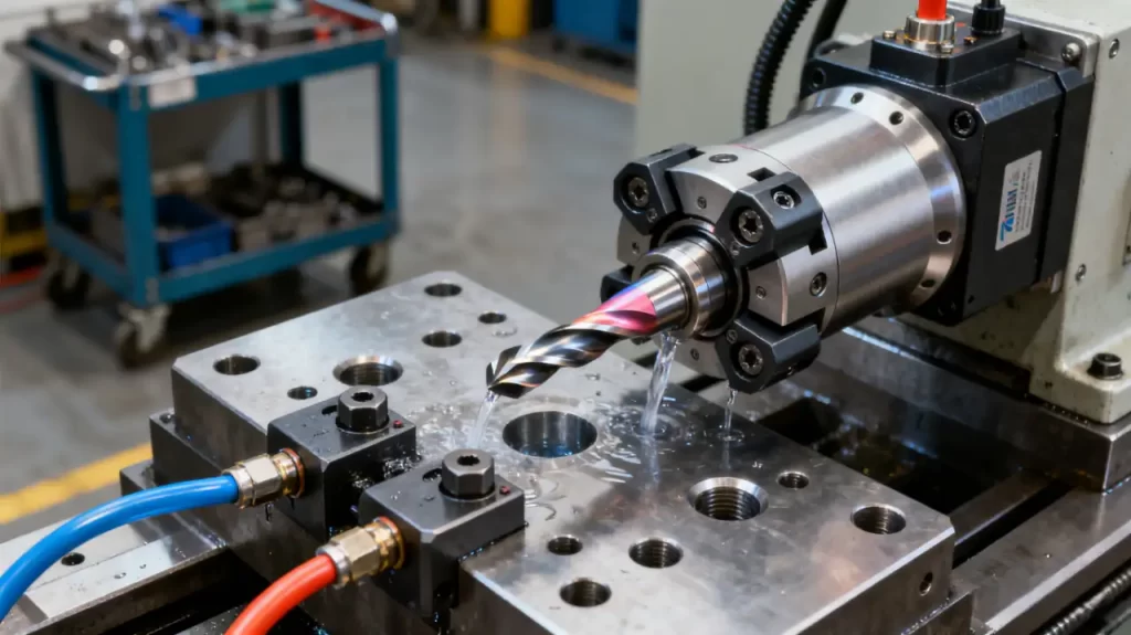
Milling machines can securely hold standard twist drills through common tooling interfaces:
- Straight-shank drills: Held via collet in milling machine systems (e.g., ER25, ER32), offering runout < 0.01 mm — sufficient for IT8 tolerance holes.
- Taper-shank drills: Mounted directly in 7:24 taper toolholders (e.g., BT40), providing superior rigidity for larger diameters (Φ10–Φ32 mm).
Key Data:
- ER collet runout ≤ 0.005 mm — meets precision hole requirements.
- Hydraulic toolholders deliver clamping torque up to 200 N·m (BT40), far exceeding the ~45 N·m required for a Φ20 mm drill in steel.
3.2 Motion Control and CNC Cycles
Modern CNC milling machines simplify drilling through canned cycles:
- G81 (Standard Drilling): For shallow holes with depth-to-diameter ratio < 3:1.
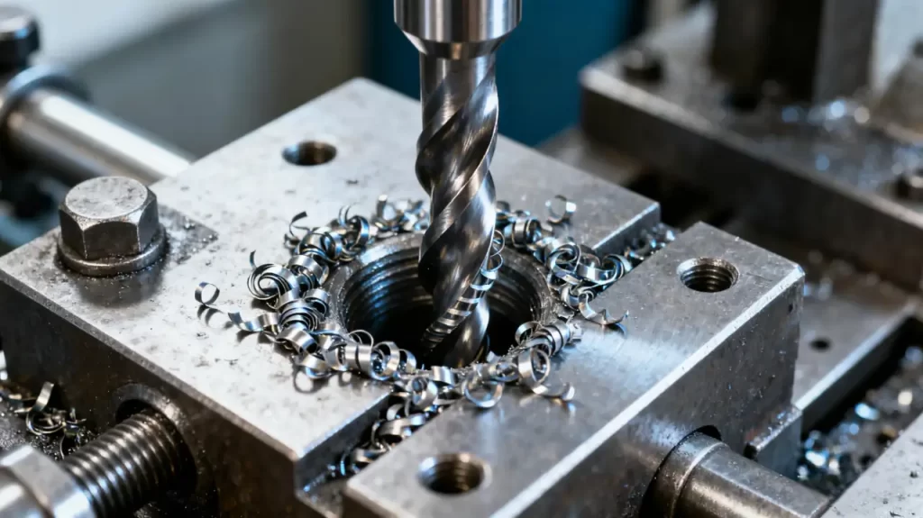
- G83 (Peck Drilling): Essential for deep holes. When to use peck drilling cycle (G83) on a CNC milling machine? Use it whenever depth exceeds 5× diameter. The cycle retracts the drill fully after each peck (e.g., Q = 5 mm), breaking chips and preventing clogging or breakage.
Manual milling machines can achieve ± 0.05 mm depth repeatability using calibrated handwheels and mechanical stops.
4. Engineering Limitations and Risk Mitigation
4.1 Efficiency and Economic Trade-offs
While technically feasible, drilling on milling machines is slower for high-volume production:
- Tool change + setup time: 30–60 seconds per hole vs. < 10 seconds on a dedicated drill press.
- Economic breakeven: For batches > 50 holes, a drill press reduces total cycle time by 30%+.
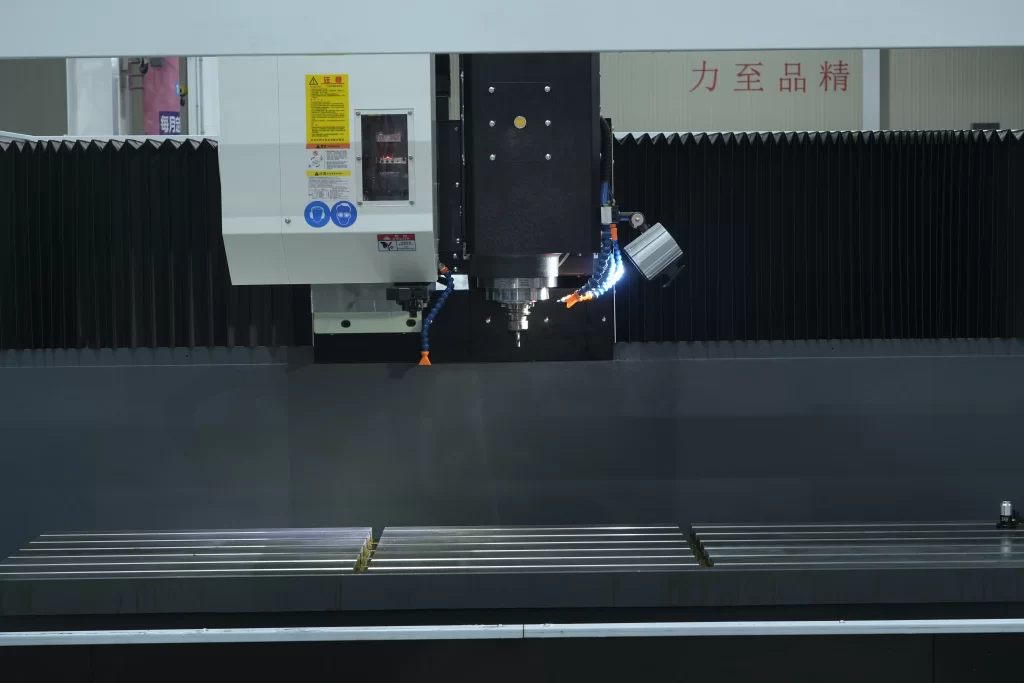
4.2 Structural and Dynamic Risks
Longer spindle overhang reduces stiffness exponentially (deflection ∝ L³). This leads to:
- Hole oversize or bell-mouthing due to drill deflection.
- Increased tool wear and breakage — carbide drill fracture rates rise by 40% under vibration.
- Accelerated wear on Z-axis ball screws and guideways under sustained thrust (> 3 kN).
4.3 Safety Protocols and Red Flags
Never:
- Use dull drills (flank wear > 0.3 mm) — cutting forces can double, risking catastrophic breakage.
- Clamp workpieces with single-point fixtures — insufficient resistance to thrust causes rotation or ejection.
- Wear gloves — entanglement in chips or rotating tools accounts for 37% of machine-related injuries.
Always:
- Install transparent guarding (mandatory on CNC machines).
- Use through-spindle coolant (≥ 5 MPa pressure) for deep holes — critical to how to prevent drill bit breakage on a milling machine.
- Enable spindle load monitoring — automatic shutdown on overload prevents milling machine spindle damage from drilling.
4.4 Process Exclusions (Do Not Drill These on a Mill)
| SCENARIO | RISK | RECOMMENDED ALTERNATIVE |
|---|---|---|
| Holes > Φ25 mm in steel | Insufficient spindle torque — risk of stalling | Use a radial drill or a boring mill |
| Depth-to-diameter ratio > 8:1 | Chip packing, tool fracture | Gun drilling with guide bushing or EDM |
| Materials > HRC45 | Rapid tool wear — < 5 holes per drill | Pre-drill + carbide drill or laser drilling |
| Thin walls (< 3 mm) | Deflection under thrust — hole mislocation | Backing support + reduced feed (0.02 mm/rev) |
These constraints define the limitations of drilling on a milling machine.
5. Optimizing Drilling Performance on Milling Machines
5.1 Tooling and Workholding Strategies
Tool Selection:
- Short-flute drills (L ≤ 3×D) minimize overhang-induced vibration.
- Internal-coolant drills (≥ 7 MPa) boost chip evacuation efficiency by 60% in deep holes.
- TiAlN-coated drills offer 3× longer life in stainless or titanium.
Workholding:
- Hydraulic or shrink-fit toolholders — runout < 0.003 mm for precision holes.
- Avoid drill chucks — radial runout > 0.05 mm compromises accuracy. Choosing the right drill bit holder for milling machine drilling is the first step to quality.
5.2 Cutting Parameter Optimization
Speed & Feed Formulas:
- Cutting Speed (Vc, m/min) = π × D × n / 1000 → n = (1000 × Vc) / (π × D)
Example: Φ10 mm drill in steel (Vc = 25 m/min) → n = 796 RPM - Feed Rate (f, mm/rev):
- Steel: 0.1–0.2 mm/rev
- Aluminum: 0.2–0.4 mm/rev
- Stainless: 0.05–0.1 mm/rev
The milling machine feed rate formula is non-negotiable. Incorrect parameters are the leading cause of risks of using milling machine as drill press.
Peck Drilling (G83) Parameters:
- Peck Depth (Q): 1.5–3 × D (e.g., Φ8 mm → Q = 12–24 mm)
- Retract Height (R): 2–5 mm above part surface
- Dwell Time: 0.5–1.0 sec (aids chip breaking)
5.3 Fixturing and Auxiliary Aids
- Drill Jigs & Bushings: For angled or curved surfaces — maintain hole position within ± 0.05 mm.
- Depth Control: Mechanical stops + dial indicators (± 0.02 mm) or CNC with linear scales (± 0.005 mm).
- Clamping: 3-point support + dual-bolt clamping — increases resistance to tipping moment by 50%.
6. Conclusion: Engineering Decision Framework
After evaluating technical capability, economic efficiency, and safety risk, here’s the definitive guidance:
Use milling machines for drilling when:
- High positional accuracy is required (IT7 or better) — milling machine vs drill press for precision holes favors the mill.
- Integrated operations are needed (mill plane → drill hole → tap thread in one setup).
- Low-volume, complex, or non-standard holes (angles, steps, countersinks).
Do NOT use milling machines for drilling when:
- High-volume production (> 100 holes/day).
- Large diameters (> Φ25 mm in steel) or extreme depth-to-diameter ratios (> 8:1) — this is the core reason for why you shouldn’t use a milling machine for heavy-duty drilling.
- Hard materials (HRC > 45) in continuous runs.
Critical Best Practices:
- Use short-reach, high-rigidity toolholders (hydraulic or shrink-fit).
- Strictly adhere to milling machine drilling parameters for steel (or other materials).
- Always use peck drilling + through-coolant for deep holes.
- Employ optimal clamping methods for drilling on a milling machine — workholding must resist both thrust and torque.
In precision manufacturing, the drilling capability of milling machines is a powerful asset — but not a universal replacement for dedicated equipment. Engineers must balance precision, throughput, cost, and safety to maximize equipment ROI and ensure operator safety.