A Comprehensive Guide to CNC Machining Parameters
In modern CNC machining, selecting the right parameters is not just about speed or feed—it’s about understanding the underlying physics of cutting, material behavior, and system dynamics. From aerospace to medical devices, CNC machining drives precision manufacturing, and mastering its core parameters—cutting speed, spindle speed, feed rate, depth of cut, cooling, and toolpath—is essential for achieving efficiency, accuracy, and long tool life.
This guide breaks down each parameter with a focus on real-world application, mechanistic insight, and process matching across materials like aluminum, stainless steel, titanium, bronze, and ceramics. Whether you’re optimizing for cnc precision machining, micro machining, or high-volume automated machining, these principles apply across the spectrum of CNC machining operations.
1. Cutting Speed (SFM) — The Core Driver of Heat Generation and Material Response
Cutting speed, measured in surface feet per minute (SFM), refers to the actual linear velocity at which the cutting edge travels across the workpiece surface. It’s not just how fast the spindle spins—it’s how fast the tool tip moves relative to the material, and it depends directly on tool diameter.
To calculate the required spindle speed (RPM), use this formula:
RPM = (SFM × 12) ÷ (π × Diameter)
For example, when using a 0.5-inch end mill to machine aluminum with a recommended SFM of 800, the spindle should run at approximately 6,110 RPM.
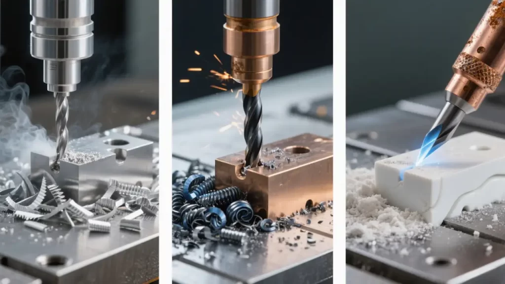
Different materials respond very differently to cutting speed due to variations in thermal conductivity, hardness, and plasticity. In high-precision CNC machining applications like cnc precision machining and micro machining, selecting the right SFM is critical for achieving both efficiency and stability.
Aluminum: High Thermal Conductivity, But Prone to Built-Up Edge
Aluminum dissipates heat well—most of the thermal energy gets carried away by the chips. This allows for high-speed CNC machining, typically between 600–1000 SFM. However, if speeds drop below 400 SFM, the material tends to stick to the rake face, forming a built-up edge (BUE) that degrades surface finish and can even chip the cutting edge.
For optimal aluminum machining and drilling aluminum, maintain SFM above 800 to promote a “hot shear” zone where chips flow cleanly and adhesion is minimized. Use sharp-edged or PCD tools, and consider MQL (minimum quantity lubrication) for better chip control in high-speed CNC machining.
Stainless Steel: Avoid the “Sweet Spot” for Work Hardening
Stainless steels like 304 and 316 are notorious for work hardening—especially in the 150–250 SFM range, where repeated plastic deformation can increase surface hardness by over 30%, accelerating tool wear.
The solution? Go low or go high:
- Roughing: Use lower speeds (120–180 SFM) to manage heat buildup
- Finishing: Push speeds above 250 SFM to reduce dwell time and limit hardening
This dual-strategy approach is essential in cnc precision machining, where dimensional accuracy and surface integrity are non-negotiable in critical CNC machining workflows.
Titanium Alloys: Trapped Heat Demands Precision Control
Titanium (e.g., Ti-6Al-4V) has extremely low thermal conductivity (~6.7 W/mK), meaning nearly all cutting heat concentrates at the tool tip. Prolonged exposure leads to rapid coating oxidation and substrate softening.
Keep SFM strictly between 80–150, and avoid continuous deep cuts. Use interrupted cutting patterns to allow the tool to cool. For deep cavities or enclosed pockets, consider cryogenic machining or cryogenic milling—using liquid nitrogen to suppress temperatures and dramatically extend tool life in demanding CNC machining environments.
Bronze: Watch Out for Material Adhesion
Bronze offers good wear resistance and self-lubricating properties, commonly used in bearings and valves. Its machinability sits between steel and aluminum, with recommended SFM values from 100–200.
During cnc machining bronze, copper buildup on the cutting edge is a common issue. Combat this with TiN or TiCN-coated tools and robust coolant delivery to prevent “copper welding” in CNC machining operations involving copper alloys.
Ceramics: Brittle Materials Need Delicate Handling
Ceramics like alumina or zirconia are extremely hard and brittle, making conventional CNC machining difficult. But with ceramic cnc machining, complex geometries can be achieved using diamond tools.
Use ultra-fine depths of cut (<0.05 mm), low feed rates (<0.001 in/tooth), and dry or MQL conditions to prevent chipping. This process demands high machine rigidity and precision—typical in aerospace and medical device CNC machining.
2. Spindle Speed (RPM) — The Hidden Factor Behind Vibration and Stability
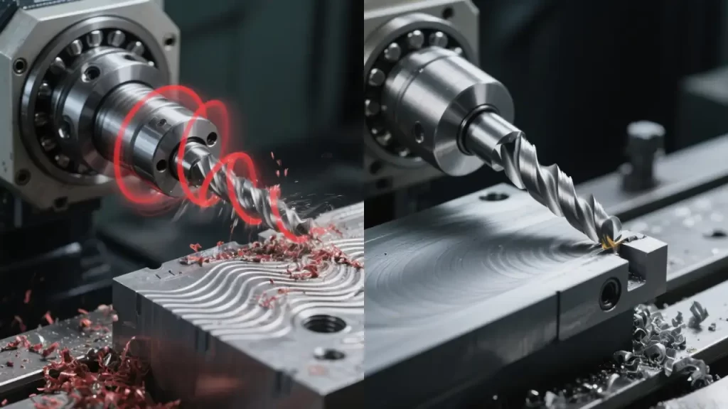
Spindle speed (RPM) determines how many revolutions the tool makes per minute. But more importantly, it influences the dynamic behavior of the entire machining system—machine, holder, tool, and workpiece together form a flexible structure with natural resonant frequencies.
When the tooth passing frequency (TPF)—how often each cutting edge engages the material—approaches one of these resonant frequencies, the system can go into chatter, producing wavy surface finishes and, in severe cases, catastrophic tool failure.
TPF (Hz) = (RPM × Number of Flutes) ÷ 60
For instance, a 4-flute end mill spinning at 12,000 RPM generates a TPF of 800 Hz. If your machine has a resonance peak near this frequency, adjust the RPM slightly—say, to 11,500 or 12,500—to break the harmonic lock.
Key Factors Affecting System Rigidity
- Tool Overhang: When overhang exceeds 4× the tool diameter, stiffness drops sharply. A 10 mm tool with 60 mm of overhang will flex easily, even at moderate speeds.
- Solutions:
- Use damping tool holders
- Reduce flute count to lower excitation frequency
- Choose variable helix or unequal flute spacing to scatter vibration energy
Modern CNC controls feature look-ahead functionality, which slows the feed rate before sharp corners or interruptions, preventing sudden load changes. This is standard in both vertical machining centers (VMCs) and horizontal machining centers (HMCs), and greatly improves performance in cnc routing and wood cnc applications—key segments of CNC machining in general manufacturing.
3. Feed Rate and Feed per Tooth — Controlling Chip Formation and Surface Quality
Feed rate, measured in inches per minute (IPM), describes how fast the tool moves across the workpiece. It’s determined by three factors: spindle speed, feed per tooth, and number of flutes.
IPM = RPM × Feed per Tooth × Number of Flutes
Example: 6,000 RPM, 0.002 in/tooth, 4-flute tool → 48 IPM
The Critical Role of Minimum Chip Thickness
Each tool material has a minimum effective chip thickness. Below this threshold, the edge doesn’t cut—it rubs, causing smearing, poor surface finish, and accelerated wear.
- Carbide tools: ~5–10 μm
- PCD tools: ~2–5 μm
- HSS tools: ~8–15 μm
In fine finishing, where feed per tooth may be as low as 0.0005 in, machine backlash can cause “stick-slip” motion—where the tool hesitates, then suddenly advances—leaving behind unwanted gouges.
Material-Specific Feed Recommendations
| MATERIAL | RECOMMENDED FEED PER TOOTH |
|---|---|
| Aluminum | 0.004–0.010 in/tooth |
| Stainless Steel | 0.002–0.006 in/tooth |
| Titanium | 0.001–0.004 in/tooth |
For deep slots or enclosed cavities, avoid full-width cuts. Instead, use trochoidal (arc-swipe) milling—moving the tool in small-radius arcs, engaging only 10–15% of its diameter per pass. This keeps cutting forces steady and reduces deflection. This method is widely used in cnc routing, including cnc wood routing, where tool rigidity is often limited—a common challenge in general CNC machining setups.
4. Depth of Cut (DOC & WOC) — The Structural Foundation of Cutting Forces
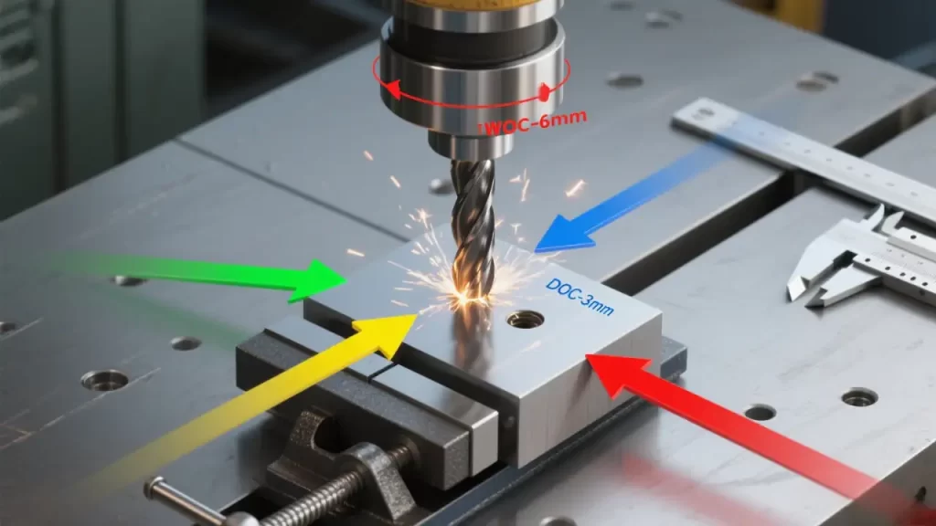
Depth of cut is split into two components:
- Axial Depth of Cut (DOC): How deep the tool plunges along the Z-axis
- Radial Depth of Cut (WOC): How much of the tool’s diameter engages the material in X/Y
Together, they define the cross-sectional area of the chip, directly influencing power demand and cutting forces.
Three Components of Cutting Force
- Tangential Force: Drives power consumption
- Feed Force: Loads the feed drive system
- Radial (Passive) Force: Acts perpendicular to feed direction—does no useful work, but can bend thin-walled parts or cause chatter
For example, milling mild steel (AISI 1045) with a 12 mm, 4-flute carbide end mill at 3 mm DOC and 6 mm WOC can generate over 1,300 N of tangential force. If the workpiece isn’t clamped securely or lacks rigidity, even slight movement can lead to dimensional errors in CNC machining.
Deep Cavity Machining Tips
When cavity depth exceeds 3× tool diameter, chip evacuation becomes a major challenge. Limit WOC to ≤30% of diameter, and use internal coolant tools with high-pressure delivery (≥70 bar) to blast chips out from the bottom.
Otherwise, chips recirculate, increasing wear and risk of edge chipping—an issue frequently encountered in deep-pocket CNC machining.
Roughing vs. Finishing Strategies
| OPERATION | DOC | WOC |
|---|---|---|
| Roughing | 1–2× Diameter | 0.5–0.8× Diameter |
| Finishing | 0.1–0.3× Diameter | 0.1–0.2× Diameter |
This staged approach maximizes material removal in roughing while ensuring surface quality in finishing—a fundamental principle in efficient CNC machining.
5. Cooling and Thermal Management — The Silent Determinant of Tool Life
During cutting:
- ~70% of heat leaves with the chips
- ~15% goes into the tool
- ~10% into the workpiece
Coolant isn’t just about cooling—it lubricates the rake face, reduces friction, and prevents built-up edge formation.
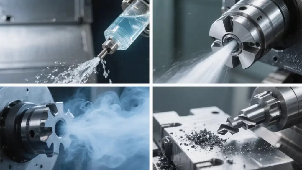
Cooling Strategies in CNC Machining: A Comparative Guide
| METHOD | PROS & CONS | BEST FOR |
|---|---|---|
| External Flood | Simple, but limited penetration (10–20 m/s jet speed) | General-purpose milling |
| Internal Coolant | High-speed jet (80–120 m/s) reaches shear zone | Deep holes, deep pockets |
| MQL (Minimum Quantity Lubrication) | Tiny oil mist (0.01–0.05 ml/min), eco-friendly | High-speed aluminum machining, micro-drilling |
| Dry Cutting | No fluid, clean shop floor | Cast iron (graphite acts as lubricant), green manufacturing |
Studies show internal coolant can extend tool life by 2–3×, especially in drilling and deep slotting. MQL shines in automated environments where fluid handling is a burden. Choosing the right cooling method isn’t just about temperature—it’s a strategic decision that affects tool life, surface quality, and environmental compliance in CNC machining environments.
6. Toolpath and Mechanical Behavior — From Geometry to Force Control
Climb Milling vs. Conventional Milling
- Climb Milling (Down Milling): Tool rotation matches feed direction. Chip thickness starts thick and tapers off. Smoother cutting, less vibration, better finish—ideal for finishing and thin-walled parts.
- Conventional Milling (Up Milling): Chip thickness starts at zero. Initial rubbing causes work hardening. Use only when cutting through cast skins or scale.
Corner Engagement and Entry Strategies
At sharp internal corners, the arc of contact suddenly increases—so does cutting force—risking chatter or tool breakage.
Solutions:
- Use arc-in entry with radius ≥1.5× tool diameter
- Program a feed slowdown near corners (e.g., from 100 to 60 IPM)
- Apply trochoidal paths to maintain constant engagement
Adaptive Clearing in Roughing
Modern CAM systems use adaptive clearing algorithms that adjust stepover and depth based on remaining stock. This minimizes air cutting, reduces cycle time, and maintains consistent tool load. Widely used in flexible manufacturing systems (FMS) and automated machining lines to enhance cnc precision machining productivity—a key advancement in modern CNC machining.
7. CNC Machining Across Industries: Parameter Adaptation by Sector
Different industries demand different parameter strategies:
| INDUSTRY | MATERIAL | KEY CHALLENGE | SOLUTION |
|---|---|---|---|
| Medical Devices | Titanium implants | Ultra-fine surface, no contamination | Cryogenic machining+ 5-axis |
| Mold & Die | Hardened steel (HRC 50+) | Thermal distortion control | CBN tools, SFM > 600 |
| Electronics | Ceramic substrates | Crack-free micro-machining | Ceramic cnc machining+ laser hybrid |
| Automotive | Cast iron engine blocks | High-volume, green production | Dry milling using graphite lubrication |
Advanced CAM platforms like Mastercam Dynamic Milling and Siemens NX Adaptive Clearing enable intelligent toolpaths. CNC look-ahead ensures smooth motion. Emerging AI-driven parameter recommendation systems analyze historical data to auto-generate optimal SFM, feed, and depth combinations—boosting efficiency in automated machining and cnc precision machining workflows, and redefining the future of CNC machining.
8. Real-World Mistakes and How to Tune Parameters
Mistake #1: Too Slow in Titanium
Running titanium at SFM < 80 prevents adequate softening, leading to adhesion, BUE, and edge chipping.
Fix: Stay within 80–150 SFM, use intermittent cutting, or apply cryogenic milling.
Mistake #2: No Cooling in High-Speed Aluminum
At SFM > 800, heat builds rapidly. Without MQL or internal coolant, thermal expansion causes dimensional drift.
Fix: Use MQL to maintain thermal stability and chip control.
Parameter Tuning Workflow
- Start with recommended values
- Conduct test cuts
- Monitor cutting forces (with dynamometer)
- Inspect chip morphology and surface finish
- Iterate until stable, efficient performance is achieved
Document the final setup for future reference—a best practice in professional CNC machining environments.
Final Thoughts: A Practical Path Forward in CNC Machining
Don’t rely on “universal parameter tables.” True CNC machining success comes from understanding why certain parameters work, not simply copying recommended values. Use standard parameters as a starting point, not an end point.
Perform controlled test cuts, observe tool wear microscopically, and measure surface roughness pass by pass. If you have a dynamometer, monitor sudden force fluctuations during corners or deep cuts. When chipping occurs during rough machining of titanium alloys, ask: Is the WOC too high? Insufficient SFM? Or is it poor chip evacuation?
Adjust incrementally, documenting every change, and build a cutting database tailored to your equipment, tools, and workshop environment. The difference between excellent CNC machining and mediocrity lies not in the quality of your equipment but in process discipline.
- For aluminum machining, verify the stability of the MQL flow rate at 800+ SFM.
- For bronze CNC machining, check for copper chip adhesion every five parts.
- For ceramic CNC machining, confirm that spindle runout is less than 3 μm; otherwise, micro-chipping is inevitable.
These details are the difference between stable production and frequent firefighting. Mastering them will not only improve part quality and tool life, but also give you true control over your machining process.